Control device for internal combustion engine

Inactive Publication Date: 2010-10-21
HONDA MOTOR CO LTD
View PDF10 Cites 30 Cited by
  • Summary
  • Abstract
  • Description
  • Claims
  • Application Information

AI Technical Summary

Benefits of technology

[0016]The primary object of the present invention, which has been made to resolve the above problems, is to provide a control device for an internal combustion engine emp

Problems solved by technology

Although such a diesel engine exhibits higher thermal efficiency compared to gasoline engines, the air-fuel mixture density in the combustion chamber tends to be highly nonuniform (due to uneven distribution of the injected (sprayed) fuel in the combustion chamber) and the combustion in the combustion chamber is likely to separate into a combustion region of spraying flames and an air region, resulting in highly uneven combustion temperature distribution in the combustion chamber.
This means that a region with excessively high fuel concentration, a region at excessively high temperature, etc.
Therefore, it is difficult to reduce both NOx and PM at the same time, and this leads to high emission of NOx and PM and a heavy load on the exhaust post-processing system.
However, combustion of all the fuel in the combustion chamber is difficult and fuel adhering to the inner surface of the cylinder is discharged without combustion, resulting in high emission of HO (hydrocarbon).
Further, the thermal efficiency tends to be relatively low in HCCI combustion since the control of ignition timing is difficult and is dependent on the temperat

Method used


Image

  • Control device for internal combustion engine
  • Control device for internal combustion engine
  • Control device for internal combustion engine

Examples


first embodiment

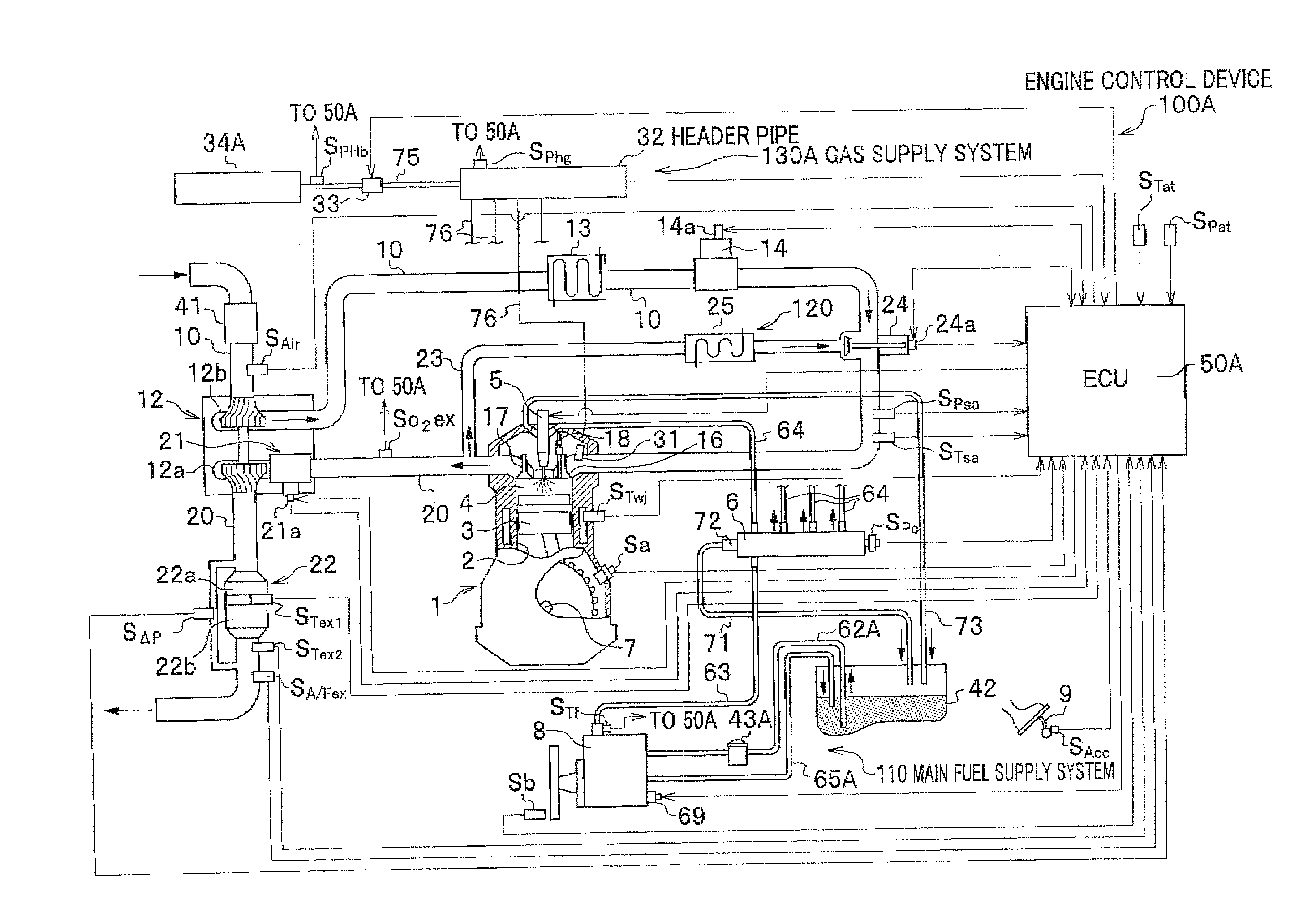
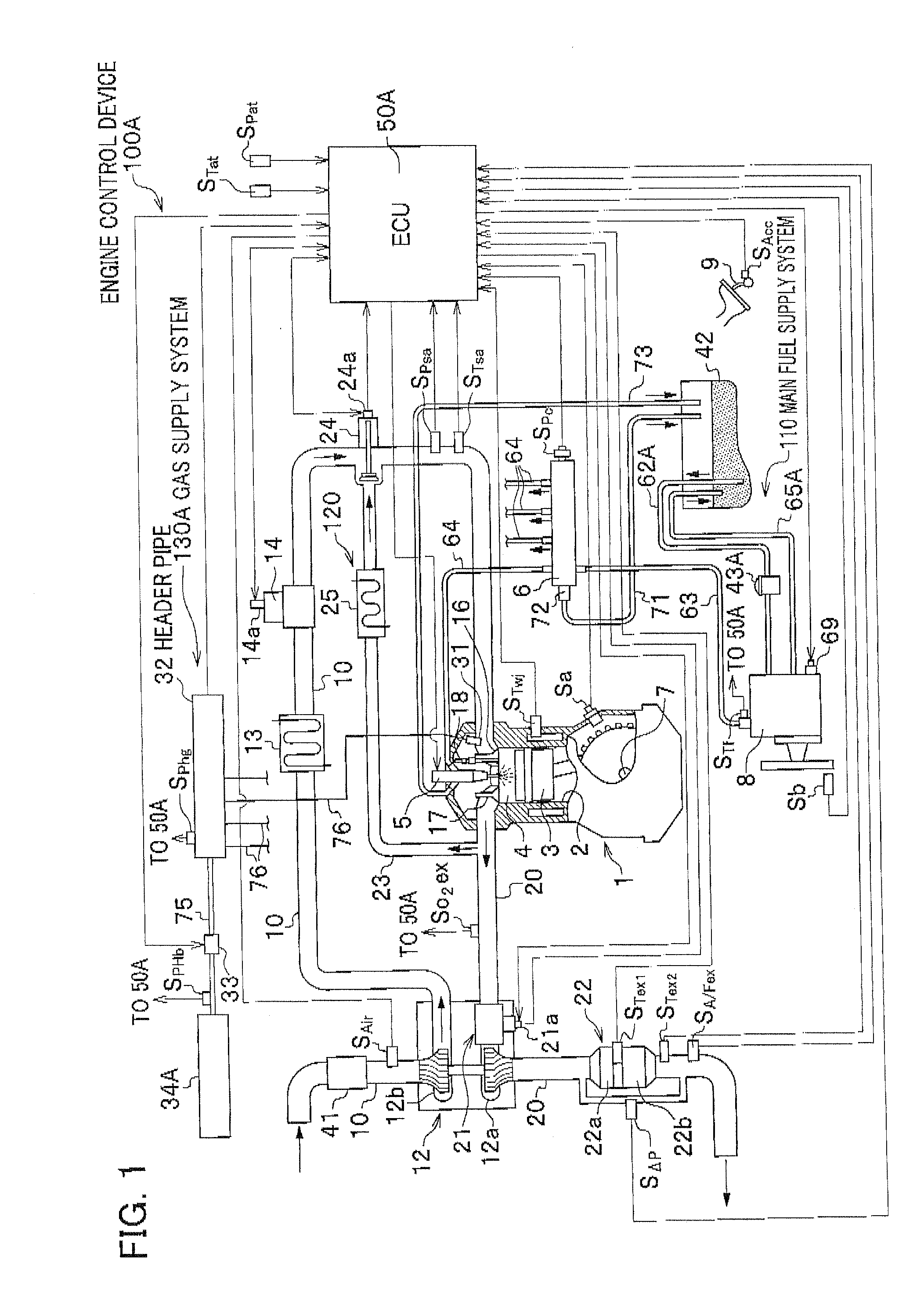
[0059]The outline of an engine control device (control device for an internal combustion engine) in accordance with a first embodiment of the present invention will be described below with reference to FIGS. 1-4.

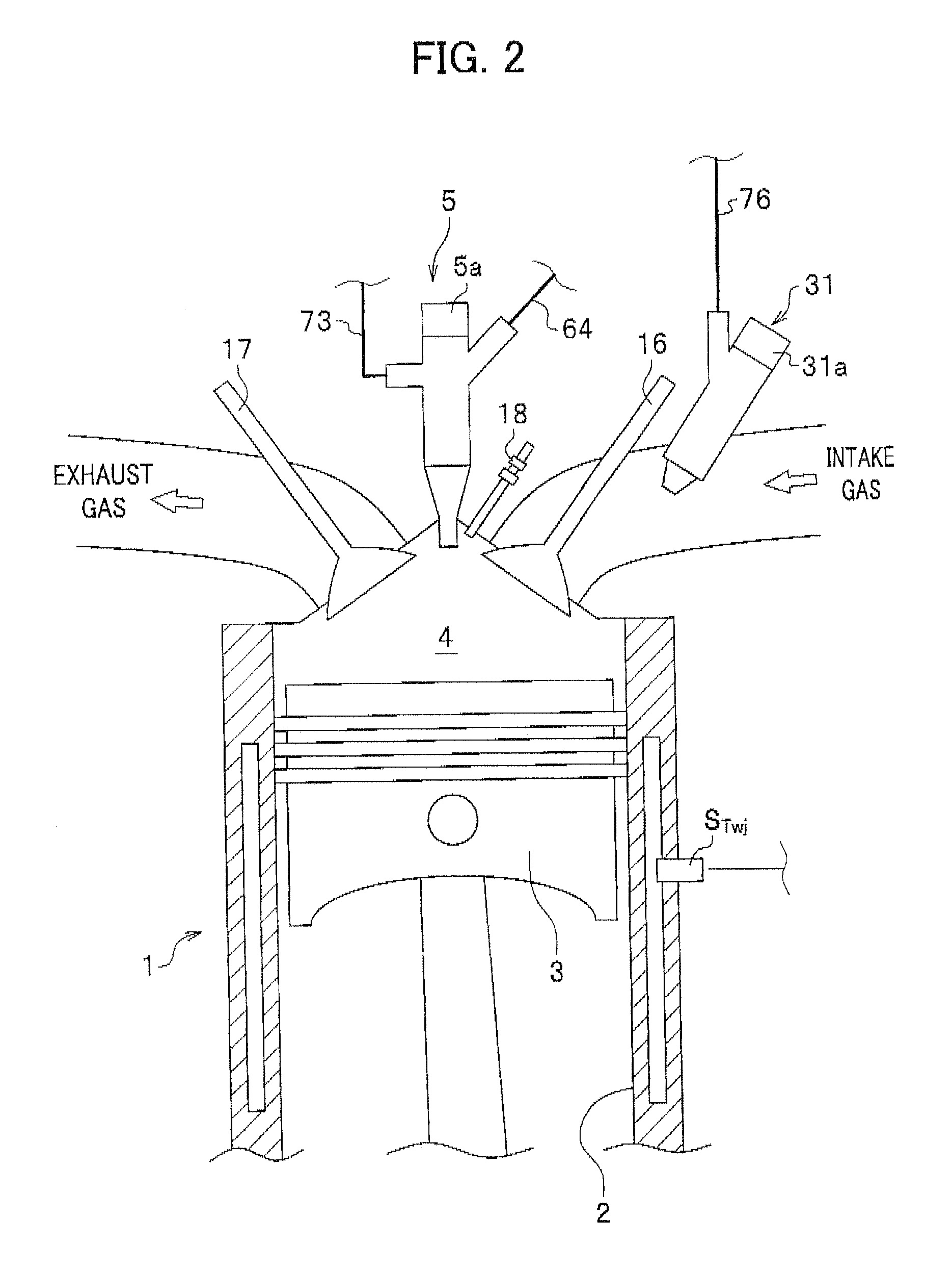
[0060]FIG. 1 is a schematic functional block diagram of the engine control device in accordance with the first embodiment. FIG. 2 is an enlarged view of a cylinder head of an engine 1 shown in FIG. 1. FIG. 3 is a schematic block diagram for explaining the hardware configuration of an engine electronic control unit which is employed for the engine control device. FIG. 4 is a functional block diagram of the engine electronic control unit.

[0061]The engine 1 (internal combustion engine) shown in FIGS. 1 and 2 is a diesel engine, in which air taken into a combustion chamber 4 formed in each cylinder 2 (intake air) is compressed by a piston 3 into a high-temperature state and self ignition is caused by injecting fuel into the compressed high-temperature intake air in the combustio...

second embodiment

[0181]In the following, the outline of an engine control device in accordance with a second embodiment of the present invention will be described with reference to FIG. 3 and FIG. 18. FIG. 3 is a schematic block diagram for explaining the hardware configuration of an engine electronic control unit employed for the engine control device. FIG. 18 is a schematic functional block diagram of the engine control device in accordance with the second embodiment.

[0182]The engine control device 100B of the second embodiment differs from the engine control device 100A of the first embodiment in that a gas supply system 130B (gas supply unit) is employed in stead of the gas supply system 130A in the first embodiment. Accordingly, an ECU 50B (combustion control unit) is employed instead of the ECU 50A in the first embodiment. In FIG. 18, components equivalent to those in the first embodiment (FIG. 1) are assigned the same reference characters as those in the first embodiment and repeated explanat...


PUM


Abstract

A control device for an internal combustion engine employing PCCI combustion, capable of realizing high-stability operation of the engine throughout a large operation area, is provided. The engine control device comprises a fuel supply system which supplies light oil or mixed fuel containing light oil to the engine, a gas supply system which supplies hydrogen to the engine, and a required premixed gas calculating unit which previously stores and uses multiple combustion waveforms (changing depending on hydrogen addition concentration) as data. The required premixed gas calculating unit selects one of the combustion waveforms so as to achieve high thermal efficiency depending on the status of the engine and determines the hydrogen addition concentration (addition concentration of the hydrogen to be supplied to the engine) corresponding to the selected combustion waveform, by which the generation of PM and NOx can be reduced while also improving the thermal efficiency of the engine.

Description

CROSS REFERENCE TO RELATED APPLICATIONS[0001]This application claims the foreign priority benefit under 35 U.S.C. §119 of Japanese Patent Application No. 2009-103251 filed on Apr. 21, 2009, the disclosure of which is incorporated herein by reference,BACKGROUND OF THE INVENTION[0002]1. Field of the Invention[0003]The present invention relates to a control device for an internal combustion engine, and in particular, to a control device for an internal combustion engine employing PCCI (Premixed Charge Compression Ignition) combustion, capable of realizing high-stability operation of the engine throughout a large operation area of the engine.[0004]2. Description of the Related Art[0005]In the conventional diffusive combustion method widely employed for diesel engines, combustion of fuel in each combustion chamber is attained by causing self ignition of the fuel, by compressing air introduced into the combustion chamber and injecting the fuel into the compressed air. Although such a dies...

Claims


Application Information

Patent Timeline
IPC IPC(8): F02D41/00F02B43/00F02B43/10
CPCF02D41/0025Y02T10/128F02M25/10Y02T10/12
Inventor KABASHIMA, HAJIMEURATA, YASUHIROYAMAMOTO, KAZUSHI
Owner HONDA MOTOR CO LTD
Why Eureka
Try Eureka