High Aspect Ratio Microstructures and Method for Fabricating High Aspect Ratio Microstructures From Powder Composites

a technology of high aspect ratio and microstructure, which is applied in the direction of coating, transportation and packaging, nuclear engineering, etc., can solve the problems of high pressure, inability to use metal powder mixtures, and inability to meet the requirements of injection molding, and achieve high aspect ratio and high precision

Inactive Publication Date: 2010-11-04
CREATV MICROTECH
View PDF14 Cites 28 Cited by
  • Summary
  • Abstract
  • Description
  • Claims
  • Application Information

AI Technical Summary

Benefits of technology

[0011]Accordingly, it is an object of exemplary embodiments of the present invention to use a lithographically defined parent mol

Problems solved by technology
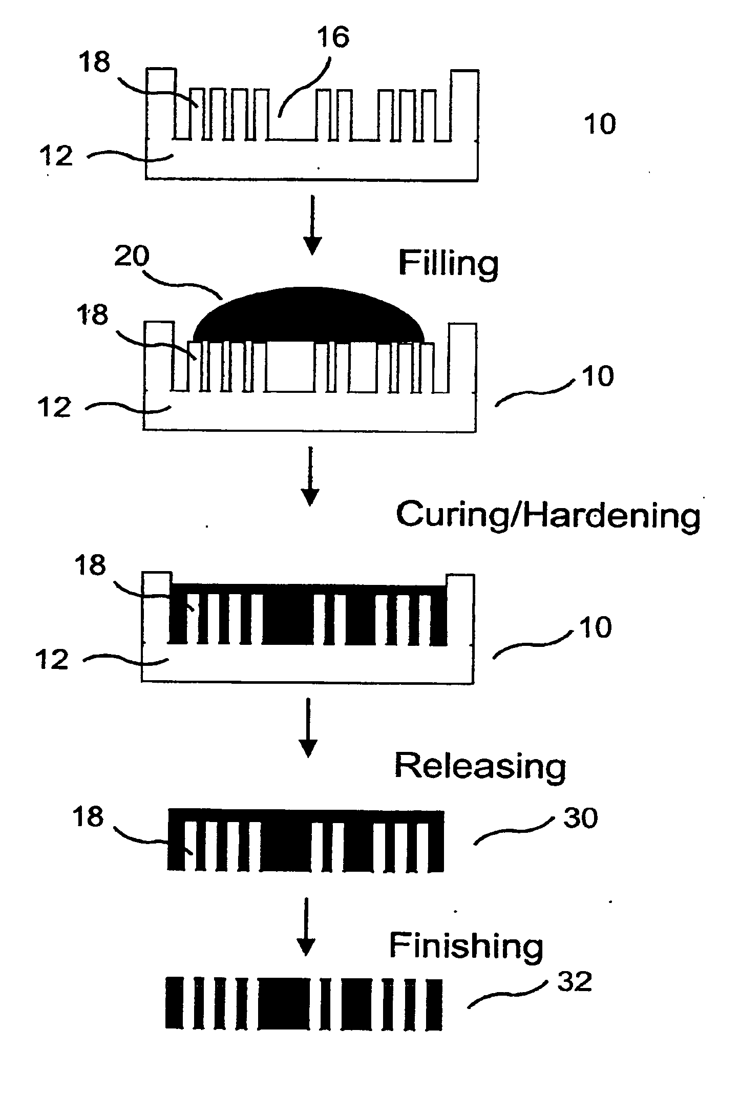
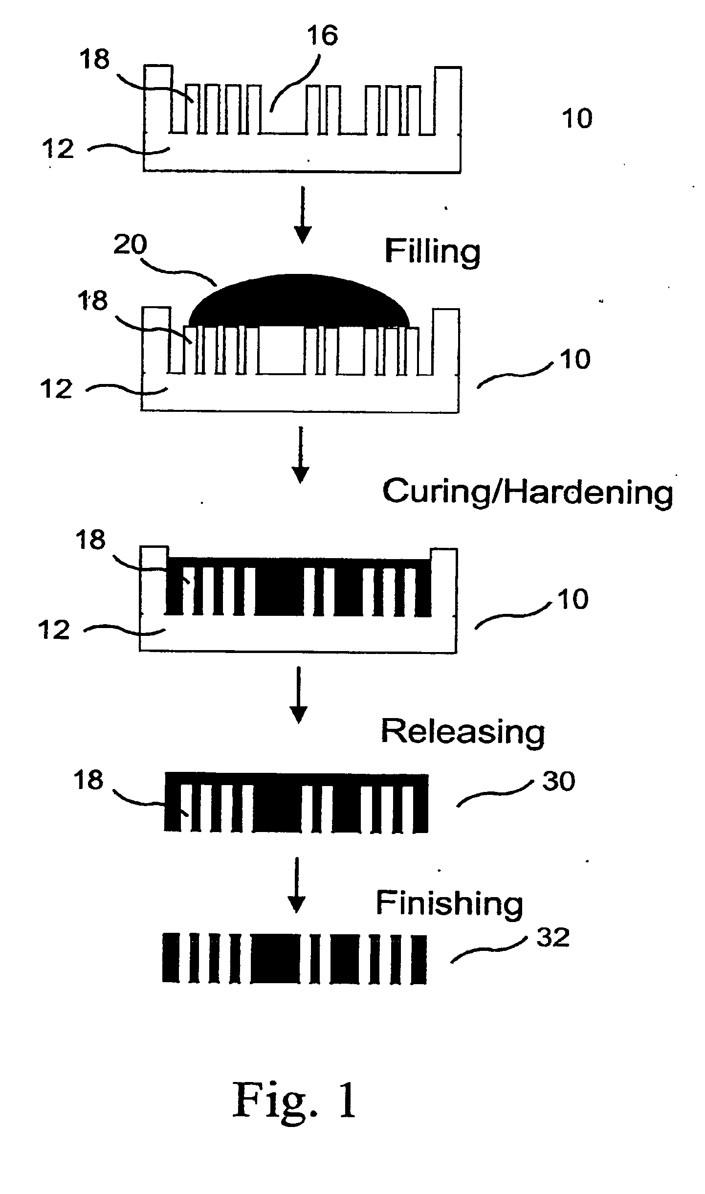
Injection molding described in this patent requires high pressure and does not provide for use of metal powder mixtures to make composite metal grids and collimators.
Such injection molding methods are not suitable for fabrication of microstructures, because the deformable molds and conventional mold-releasing agents cause unacceptable deformities in the microstructures.
Despite the conventional technologies described above, structures such as grids and collimators with aspect ratio larger than about 5 and an ar

Method used


Image

  • High Aspect Ratio Microstructures and Method for Fabricating High Aspect Ratio Microstructures From Powder Composites
  • High Aspect Ratio Microstructures and Method for Fabricating High Aspect Ratio Microstructures From Powder Composites
  • High Aspect Ratio Microstructures and Method for Fabricating High Aspect Ratio Microstructures From Powder Composites

Examples


example 1

[0054]This exemplary implementation describes fabrication of high aspect ratio tungsten composite grids using epoxy as the binder.

[0055]An SU-8 mold on the graphite substrate was prepared by UV lithography of 600 micron thick SU-8 negative photo resists. The SU-8 mold was patterned with a 64×64 array of square cells, surrounded with a 2 mm border. Each cell has a 341 μm×341 μm square opening separated by 39 μm septa walls. After cleaning, the mold was vapor deposited with a coating of perfluorodecanethiol.

[0056]An RTV silicone rubber mold was prepared by casting Silastic M RTV silicone resin into the prepared SU-8 parent mold. The resin base and its curing agent (ratio of 10:1 by weight) were thoroughly mixed and poured over the SU-8 parent mold, and degassed in a vacuum chamber to remove entrapped air bubbles. After curing of the silicone for 16 hours at room temperature, the elastic RTV mold was peeled from the SU-8 parent mold.

[0057]A molding composition was prepared with 9.2 g W...

example 2

[0058]This exemplary implementation describes fabrication of high aspect ratio tungsten composite collimators with low-melt, fusible metals as the binder using the alternative method as illustrated in FIG. 3.

[0059]A copper lithographic parent mold 510 comprising backing 512 and opening 516 between corresponding elevated patterns 518 was prepared by X-ray lithography. The copper lithographic parent mold is prepared as follows:[0060](a) Positive photoresist, PMMA, is attached on the graphite substrate.[0061](b) The x-ray mask is aligned onto the resist / substrate. This mask / resist / substrate assembly is then exposed at an x-ray source to transfer the pattern to the photo resist. The polymer chains are destroyed in the irradiated portions of the resist, rendering them suitable for solvent removal.[0062](c) The exposed PMMA and substrate is then developed, selectively dissolving the exposed resist while leaving the non-irradiated parts, which remain unchanged.[0063](d) Copper is electropl...


PUM

PropertyMeasurementUnit
Densityaaaaaaaaaa
Densityaaaaaaaaaa
Densityaaaaaaaaaa

Abstract

Methods to fabricate high aspect ratio powder composite microstructures is provided by filling a molding composition containing a powdered material and a binder into a patterned mold, and releasing the cured composite microstructures from the mold. An alternate method is by filling a mix of powdered dense metals and low-melt alloys into a patterned mold, and releasing the melted and solidified composite microstructures from the mold. The mold is derived from lithographically defined parent mold. One example of the application is in the field of x-ray anti-scatter grids and nuclear collimators.

Description

[0001]This application claims benefit under 35 U.S.C. §119 from U.S. Provisional Application No. 60 / 772,583, filed on Feb. 13, 2006, the entire content of which is incorporated herein by reference.FIELD OF THE INVENTION[0002]The present invention relates to high aspect ratio microstructures, a process and various methods for realizing the process of fabricating high aspect ratio microstructures from a molding composition by filling a mold or its derivative polymeric mold. This invention is applicable to the fabrication of x-ray anti-scatter grids, nuclear collimators, and other high aspect ratio structures using high-density powdered materials in combination with a polymeric or low melting temperature metal or other material. It is also applicable to the fabrication of optical components, such as optical collimators and other structures, using high and / or low-density metal, ceramic, and / or polymeric materials. The fabrication methods do not require the use of high pressure or high t...

Claims


Application Information

Patent Timeline
IPC IPC(8): B29C41/50B22F3/24B29C41/04B29C41/46B22F1/10B22F1/17
CPCB22F1/0059B22F1/025B22F2999/00B29C33/3842B29C33/424B29C39/003G21K1/06B29C41/003B29C41/045B29C39/42G21K1/025B22F3/1055B22F5/007Y02P10/25B22F1/17B22F1/10
Inventor YANG, GUOHUAMAKAROVA, OLGAAMSTUTZ, III, PLATTE
Owner CREATV MICROTECH
Why Eureka
Try Eureka