3-D Printing of near net shape products

a 3d printing and product technology, applied in the field of manufacturing of near-net-shaped products, can solve the problems of inability to produce ceramic material preforms, lack of available materials, and high-power lasers, and achieve the effect of easy handling and high porosity

Inactive Publication Date: 2010-11-04
STORM DEV LLC +1
View PDF29 Cites 122 Cited by
  • Summary
  • Abstract
  • Description
  • Claims
  • Application Information

AI Technical Summary

Benefits of technology

[0010]The invention advantageously employs greenbodys of very high porosity. The invention enables manufacture of near net shaped ceramic containing components. The components may be readily handled during secondary operations such as thermal processing and metal impregnation to produce ceramic metal composites such as siliconized silicon carbide.

Problems solved by technology

SLS, although it has advantages of speed and accuracy, is inhibited by lack of available materials for manufacture of products.
SLS also suffers from the requirement to use high-powered lasers.
LBM, although useful for manufacture of preforms such as plaster, has not been widely used to produce preforms of ceramic materials.
This is due, in part, to the high abrasiveness of the ceramic materials such as SiC on the print heads and other components of the machine.
% or more, which can be detrimental during post processing of components such as ceramic components.
In addition to the forgoing disadvantages, neither SLS nor LBM is capable of producing metal impregnated composites such as siliconized SiC.
This known method, however, suffers the disadvantage that special tools must be made for manufacture of specific components.

Method used


Image

  • 3-D Printing of near net shape products
  • 3-D Printing of near net shape products

Examples


example 1

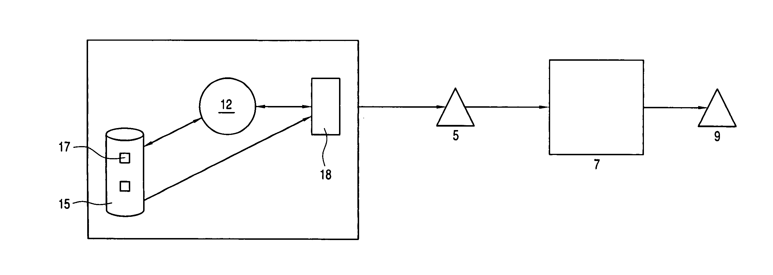
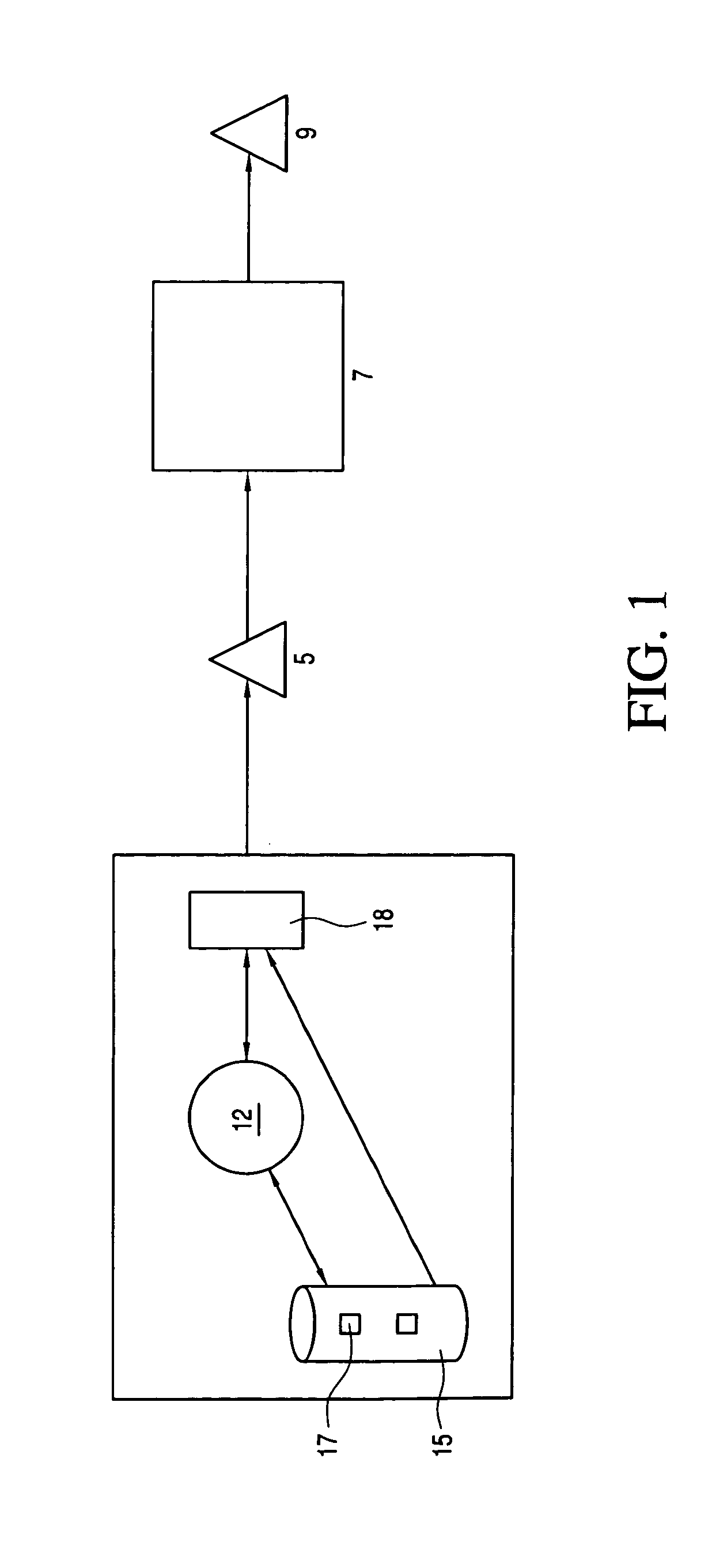
[0037]A numerical model of a heat exchanger block having the dimensions 14 inches long by 8 inches high by 10 inches wide is prepared using DESIGNPRINT software 7.3 from IDEAL Scanners and Systems, Inc. The numerical model is used as input to a Spectrum Z510 rapid prototyping LBM system machine from Z Corporation.

[0038]22680 gms of 80 grit SiC build material is combined with 2268 gms sugar binder and mixed in a bucket mixer for 3 hours to produce a BMB mixture. The mixture is added to the Spectrum Z510 rapid prototyping LBM system machine. The Spectrum Z510 rapid prototyping LBM system machine includes a feed bed, a build bed and a printer carriage assembly for supplying liquid activator to the binder.

[0039]The BMB mixture of silicon carbide and sugar is supplied to the feed bed of the LBM machine. A roller transfers a portion of the BMB mixture from the feed bed to the build bed of the machine to produce a layer of BMB mixture that has a thickness of 0.254 mm. The printer carriage ...

example 2

[0041]The method of example 1 performed except that 1134 gms of Durez 5019 phenolic resin is employed as binder, acetone activator fluid in an amount of 0.132 ml / gm of the BMB mixture is employed, and drying of the applied activator fluid is performed at 38° C. for 3 min.

example 3

[0042]The method of example 1 performed except that a mixture of 454 gms of Durez 5019 phenolic resin and 1361 gms of sugar is employed as binder, a mixture of 80 wt. % water and 20 wt. % acetone is employed as activator fluid, the activator fluid is applied in an amount of 0.088 ml / gm of the BMB mixture, and drying of the applied activator fluid is performed at 38° C. for 5 min.


PUM

PropertyMeasurementUnit
porosityaaaaaaaaaa
thicknessaaaaaaaaaa
porosityaaaaaaaaaa

Abstract

The disclosed method relates to manufacture of a near net-shaped products such as ceramic containing products such as ceramic-metal composites. The method entails forming a mixture of a build material and a binder and depositing that mixture onto a surface to produce a layer of the mixture. An activator fluid then is applied to at least one selected region of the layer to bond the binder to the build material to yield a shaped pattern. These steps may be repeated to produce a porous whitebody that is heat treated to yield a porous greenbody preform having a porosity of about 30% to about 70%. The greenbody then is impregnated with a molten material such as molten metal. Where the build material is SiC, the molten metal employed is Si to generate a SiC—Si composite.

Description

[0001]This application claims priority to U.S. Provisional Application U.S. Ser. No. 60 / 964,710 filed Aug. 14, 2007.FIELD OF THE INVENTION[0002]The invention generally relates to manufacture of near net-shaped products. More specifically, the invention relates to deposition of successive layers of compositions such as ceramic compositions to produce near net shaped ceramic products.BACKGROUND OF THE INVENTION[0003]Two well-known methods for producing products by depositing of successive layers include the selective laser sintering (“SLS”) method and the liquid binder method (“LBM”). Both of these methods deposit successive thin cross sections of material to build three-dimensional products.[0004]SLS involves spreading a thin layer of powder onto a flat surface. After the layer is spread onto the surface, a laser is directed onto selected areas of the powder to fuse those areas. Successive layers of powder are spread over previous layers followed by sintering or fusing with the laser...

Claims


Application Information

Patent Timeline
Patent Type & Authority Applications(United States)
IPC IPC(8): B05D1/06
CPCB22F3/008B28B1/00C22C32/00C04B2235/80C04B2235/6581C04B2235/6026C04B2235/5472C04B2235/5436C04B2235/5427C04B2235/48C04B2235/428C04B2235/404C04B2235/402C04B2235/3843C04B2235/3826C04B2235/3817C04B2235/3463C04B41/88C04B41/4523C04B41/009C04B35/65B28B1/001B28B7/465C04B35/117C04B35/185C04B35/484C04B35/56C04B35/565C04B35/573C04B35/58071C04B35/6269C04B35/632C04B35/634C04B35/636C04B41/4515C04B41/4578C04B41/5096C04B41/5155C04B35/10C04B35/584C04B38/00Y02P10/25B22F10/38B22F10/16
Inventor BRISELDEN, THOMAS D.REILLY, THOMAS M.FORSMAN, DAVID R.
Owner STORM DEV LLC
Why Eureka
Try Eureka