Microfluidic filtration unit, device and methods thereof

a microfluidic filtration and microfluidic technology, applied in the field of microfluidic filtration devices, can solve the problems of large particles such as red blood cells, need about 10 minutes to diffuse 10 microns, and the effect of reducing the speed at which fluid flows, reducing the flow pressure in the filtration barrier, and less sensitiv

Inactive Publication Date: 2010-11-18
AGENCY FOR SCI TECH & RES
View PDF5 Cites 16 Cited by
  • Summary
  • Abstract
  • Description
  • Claims
  • Application Information

AI Technical Summary

Benefits of technology

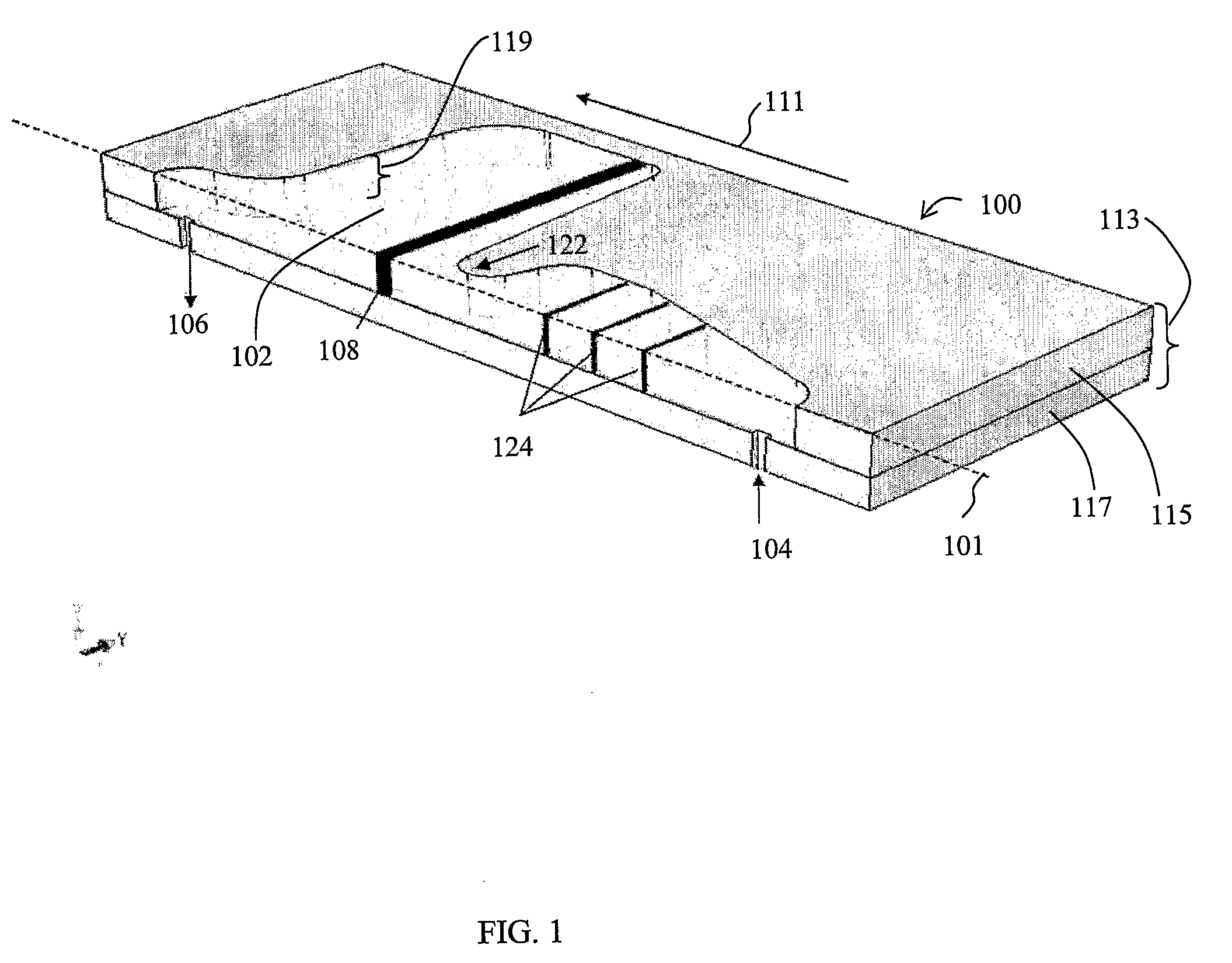
[0037]In another embodiment, the part of the fluid chamber in which the filtration barrier is located comprises an enlarged cross-sectional area relative to the cross-sectional area of the inlet through which fluid is introduced into the fluid chamber. The enlarged cross-sectional area reduces the speed at which fluid flows through the filtration barrier and thus greatly reduces flow pressure in the filtration barrier. In this manner, the filtration barrier becomes less sensitive to spikes in fluid pressure when fluid samples are injected into the unit, and thereby less prone to breakage.
[0038]When filtering fluid samples containing large particles, e.g. sediments in water samples obtained from muddy water sources, the large particles can be first separated from the fluid by implementing a coarse filter upstream of the filtration barrier. The coarse filter helps to ensure that the fluid reaching the filtration barrier contains essentially only small particles which the filtration barrier is designed to filter, and not large particles which would rapidly clog even the coarse filtration sections in the filtration barrier.
[0039]When the microfiltration unit is implemented as a stand alone filtration device, a housing may be provided to accommodate the fluid chamber and the filtration barrier. In one embodiment, the housing comprises three-sections: a planar base substrate, an intermediate planar member attached to the planar base substrate, and a transparent cover attached to the intermediate planar member. The intermediate planar member is hollow in the centre with lateral sidewalls of the planar member surrounding the hollow, said hollow being defined through the thickness of the planar member. This three-piece configuration can be easily fabricated and assembled by employing standard lamination and bonding techniques known in the art. An alternative design comprises a monolithically formed base substrate and intermediate planar member, requiring only the attachment of the transparent cover in order to obtain a complete device. For certain applications in which filtered particles are to be harvested, it is preferable to have removable covers which are conveniently removed and the filtered particles are readily accessible.

Problems solved by technology

Polymeric membranes are generally less effective for mechanical filtration.
Due to the statistical pore size distribution inherent to current fabrication techniques of polymer membranes, small and large pores are randomly formed in any given sample of the membrane filter, and particles to be captured are inevitably lost through these large pores, resulting in low trapping efficiencies.
However, larger particles, such as red blood cells, need about 10 minutes to diffuse 10 microns.
Pillar-type microfilters often suffer from high flow resistance and high sensitivity to clogging.
High sensitivity to clogging means that the filter will cease to function after a relatively short period of time, as most of its available pores / opening are filled up and blocked.
High flow resistance in turn creates high hydrodynamic pressure at the filters.
This not only creates difficulties in the injection of the sample into the device, but may bring about the breakage of the microfiltration unit.
Furthermore, cell membranes of ‘captured’ cells may be damaged by the high pressure and thus rendered useless for analysis.
In all the above pillar-type microfiltration units, one frequently encountered problem is that the upstream filters are clogged after a short period of use, and fluid is eventually unable to flow through the filter, thereby leading to high pressure and potential breakage.
Unless it is carefully monitored over the course of filtration, the parts of the microfiltration unit tends to be mechanically weakened or even break from the spike in hydrodynamic pressure, leading to leaks and loss of filtered particles and filtrate.

Method used


Image

  • Microfluidic filtration unit, device and methods thereof
  • Microfluidic filtration unit, device and methods thereof
  • Microfluidic filtration unit, device and methods thereof

Examples


example 1

Fabrication

[0072]The raindrop shaped pillars were fabricated by standard micromachining techniques. According to one process scheme which the inventors have developed for this invention, the following process steps were carried out to fabricate the pillars as shown in FIG. 9. Firstly, a resist mask was patterned, using silicon dioxide as hard mask (FIG. 9A). The oxide hard mask was subsequently opened and deep silicon etching was carried out to achieve an etch depth of about 30 μm (FIG. 9B). The oxide hard mask was then removed and the etched-out gaps were filled (FIG. 9C). By employing conformal deposition to fill the gaps, filter channel gaps were accurately fabricated down to sub-micron ranges. The subsequent step comprises backside wafer patterning to form the inlet and outlet opening of the fluid chamber (FIG. 9D). The nitride and oxide mask is then opened (FIG. 9E) and etching is performed (e.g. using KOH on Si) to form the inlet and outlet (FIG. 9F). Finally, the lamination a...

example 2

Characterization

i) Pressure Drop Test

[0077]An experiment was carried out to compare pressure drop characteristics between the microfiltration unit according to the present invention and a microfiltration unit without by-pass coarse sections. For the experiment, a microfiltration unit comprising diamond shaped pillars arranged in a zig-zag configuration without by-pass ('zig-zag filter', Chip 1) as shown in FIG. 13A was fabricated to serve as a control for the experiment. The zig-zag filter 900 comprises a fluid chamber 901 and a coarse filtration section 910 having four rows of pillars, the row nearest to the inlet 902 having a filter gap size of 50 μm, the next row having a gap size of 30 μm, and the next two rows both having the same gap size of 20 μm. Downstream of the coarse filtration section is a fine filtration region 920 comprising pillars arranged in a zig-zag formation. As can be seen from the magnified FIG. 920A, the fine filtration region 920 comprises diamond-shaped pil...


PUM

PropertyMeasurementUnit
distanceaaaaaaaaaa
distanceaaaaaaaaaa
distanceaaaaaaaaaa

Abstract

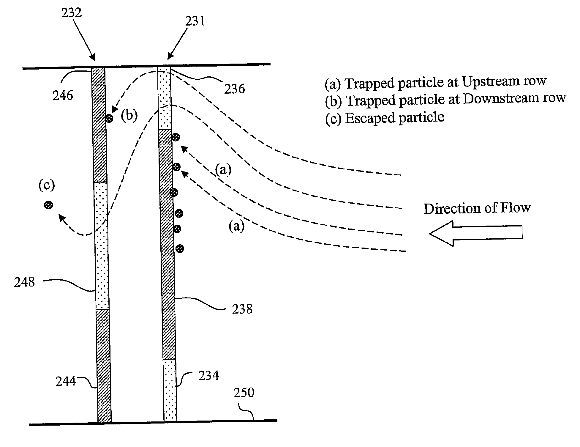
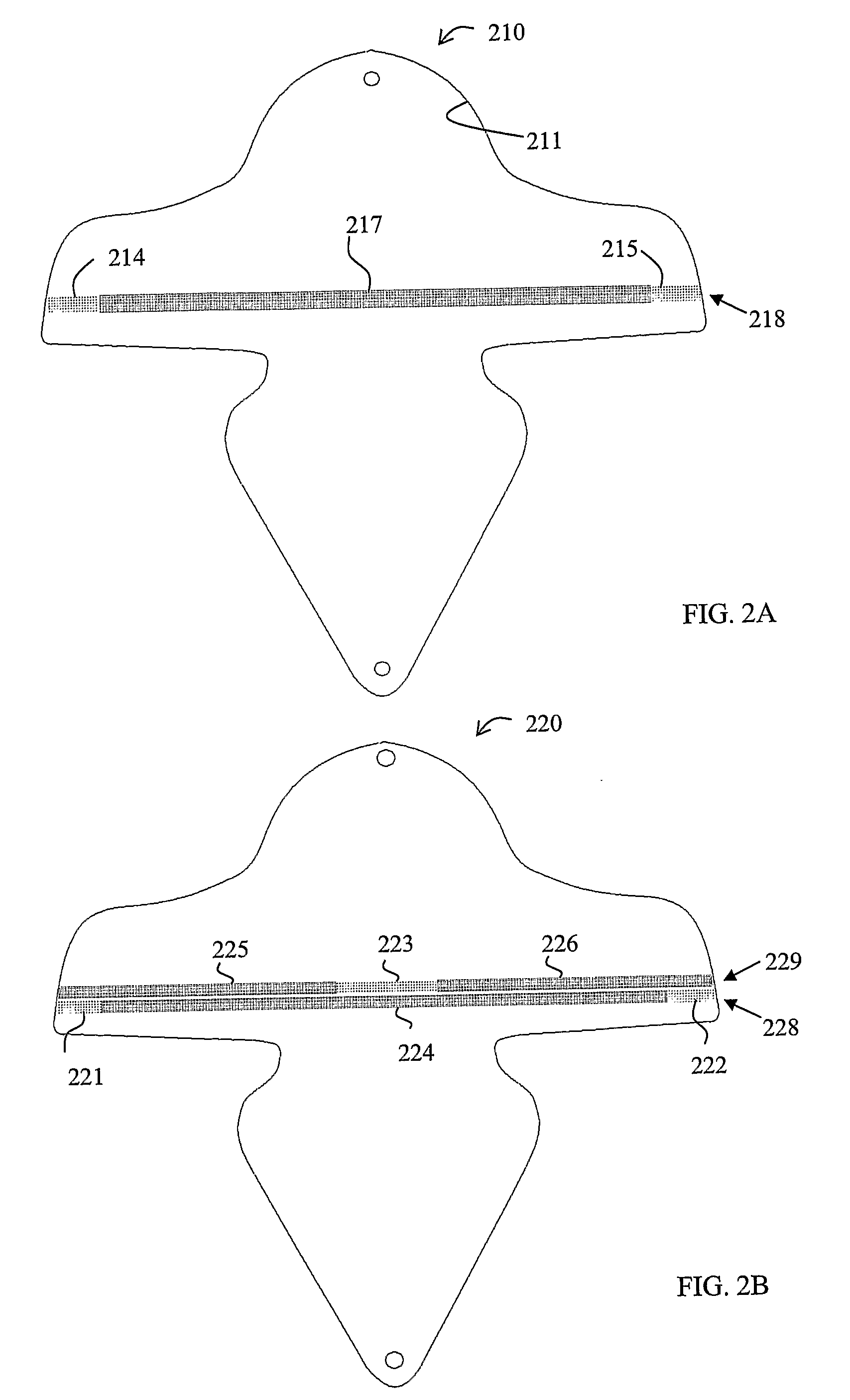
A microfluidic filtration unit for trapping particles of a predetermined nominal size present in a fluid is provided. The unit comprises a fluid chamber connected to an inlet for introducing the fluid to be filtered and an outlet for discharging filtered fluid, a filtration barrier arranged within the fluid chamber, said filtration barrier comprising a plurality of pillars arranged substantially perpendicular to the path of fluid flow when fluid is introduced into the fluid chamber, said pillars being aligned to form at least one row extending across said path of fluid flow, wherein each of said at least one row of pillars in the filtration barrier comprises at least one fine filtration section comprising a group of pillars that are spaced apart to prevent particles to be filtered from the fluid from moving between adjacent pillars, and at least one coarse filtration section comprising a group of pillars that are spaced apart to permit the movement of particles between adjacent pillars.

Description

[0001]The present invention relates to the field of microfluidics, and more particularly to microfluidic filtration units.BACKGROUND OF THE INVENTION[0002]In recent years, microfluidic filtration devices, more commonly known as microfilters, have come to play an important role in lab-on-a-chip biomolecular analytical systems in which they are required for the separation of particles with micro- and nano-scale sizes from small volumes of liquid of several hundred microlitres, typically biological samples containing microscopic cellular particles.[0003]Various types of microfilters have been developed and can be broadly categorised as either active or passive microfilters. Examples of active microfilters include ultrasonic microfilters, magnetic microfilters, and dielectrophoresis microfilters. Passive microfilters include various sieve-type microfilters. While active microfilters are capable of filtering particles present in low concentrations in a sample, conventional passive microf...

Claims


Application Information

Patent Timeline
Patent Type & Authority Applications(United States)
IPC IPC(8): B81B1/00B01D29/03B01D29/50
CPCB01D61/147G01N1/4077B01L3/5027
Inventor ZHU, LIANGLIU, WEN-TSOFENG, HANHUAJI, HONG MIAOTEO, WILLIAM CHENG YONGBADAM, RAMANA MURTHY
Owner AGENCY FOR SCI TECH & RES
Why Eureka
Try Eureka