Boiler waterwall panel

a technology of boiler water wall and water wall plate, which is applied in the direction of steam boiler components, steam boiler components, lighting and heating apparatus, etc., can solve the problems of troublesome work for welding defects, corrosion of subatrate materials, and breakdown of corrosion resistant alloy coatings, etc., to reduce welding operation burden, improve welding efficiency, and perform more easily

Inactive Publication Date: 2010-12-02
DAI ICHI HIGH FREQUENCY +1
View PDF7 Cites 8 Cited by
  • Summary
  • Abstract
  • Description
  • Claims
  • Application Information

AI Technical Summary

Benefits of technology

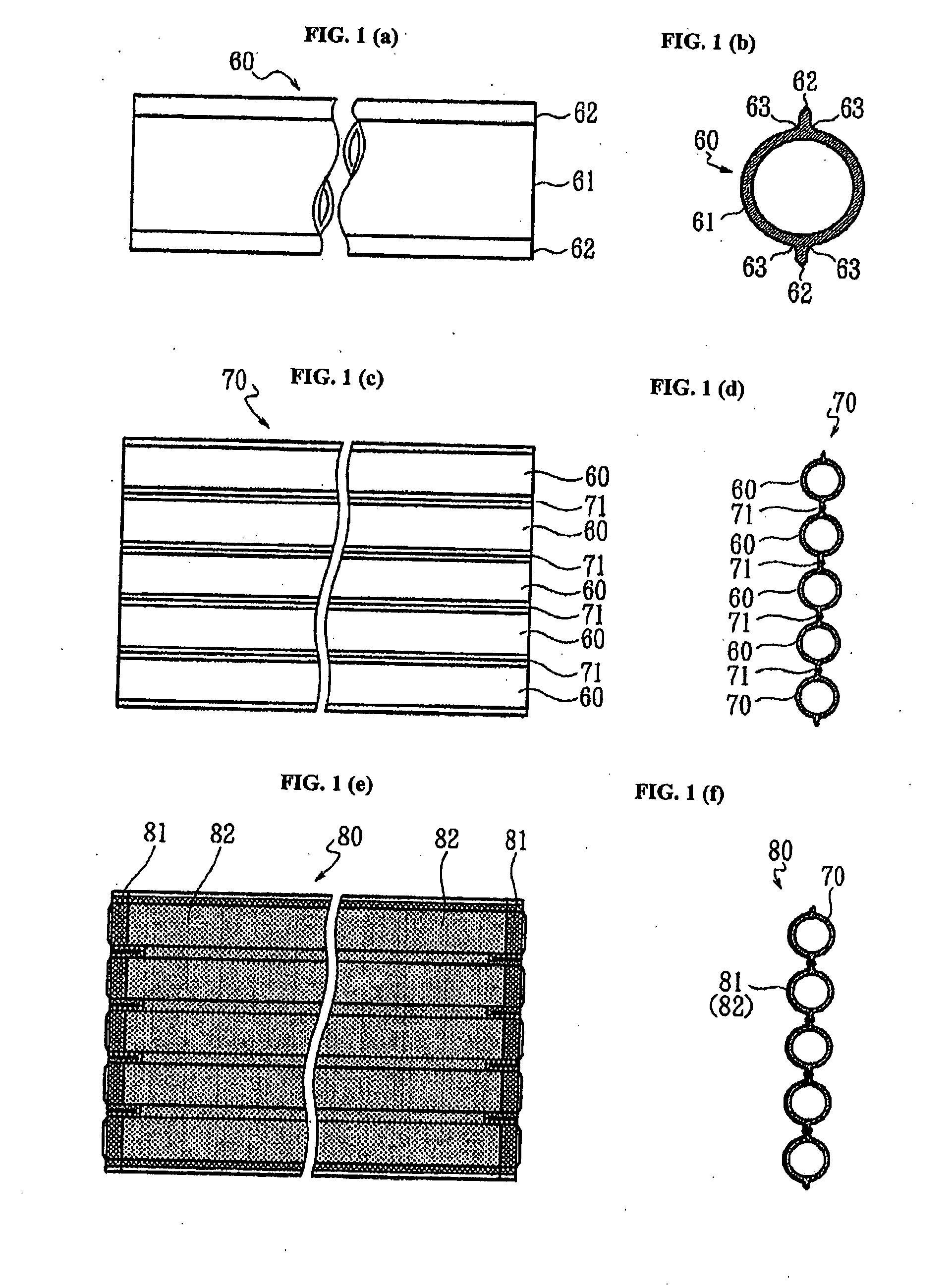
[0027]According to the boiler waterwall panel of the present invention (claim 1), since an integrally continued metal seamless finned single tube of an entire continuous phase having a tubular portion and a pair of fin portions located at opposite peripheral sides of the tubular portion and extending in the tubular axial direction capable of being produced by a hot extrusion method is employed as a constituent unit, the transition portion ranging from the tubular portion to the fin portion is not required to be welded. Furthermore, the welding of the tip ends of the fin portions can be performed more easily than the welding of the transition portion, and the welded portion is higher in quality. This reduces the burden of the welding operation for producing the boiler waterwall panel. As to the furnace housing using aforementioned boiler waterwall panels, since no welded portion exists at the transition portion, the fusion-bonded coating is free from the influence of the notch due to unevenness of the welding of this portion. Furthermore, since the welded portion formed in the middle of the web portion instead of the welded portion of the transition is high in quality, damages of the fusion-bonded coating can be remarkably reduced, resulting in a remarkably reduced necessity of the maintenance, which in turn results in stable operation and an improved operation rate of the boiler with furnace housing.
[0028]According to the boiler waterwall panel of the present invention (claim 2), since a seamless finned tube-web assembly, which is equivalent to the case in which a small number of the aforementioned integrally continued seamless finned single tubes are united with an entire continuous phase manner, then employed as a constituent unit, the transition portion ranging from the tubular portion to the fin portion is not required to be welded, too. Furthermore, the number of the welding operation for welding the tip ends of the fin portions can be reduced. This reduces the burden of the welding operation at the time of producing the boiler waterwall panel. In a furnace housing in which the boiler waterwall panel is assembled, damages of the fusion-boned coating can be further remarkably reduced.
[0029]Accordingly, in the present invention (claims 1 and 2), the burden of the welding operation at the time of producing the boiler waterwall panel can be reduced, and the operation rate of the boiler can be improved.
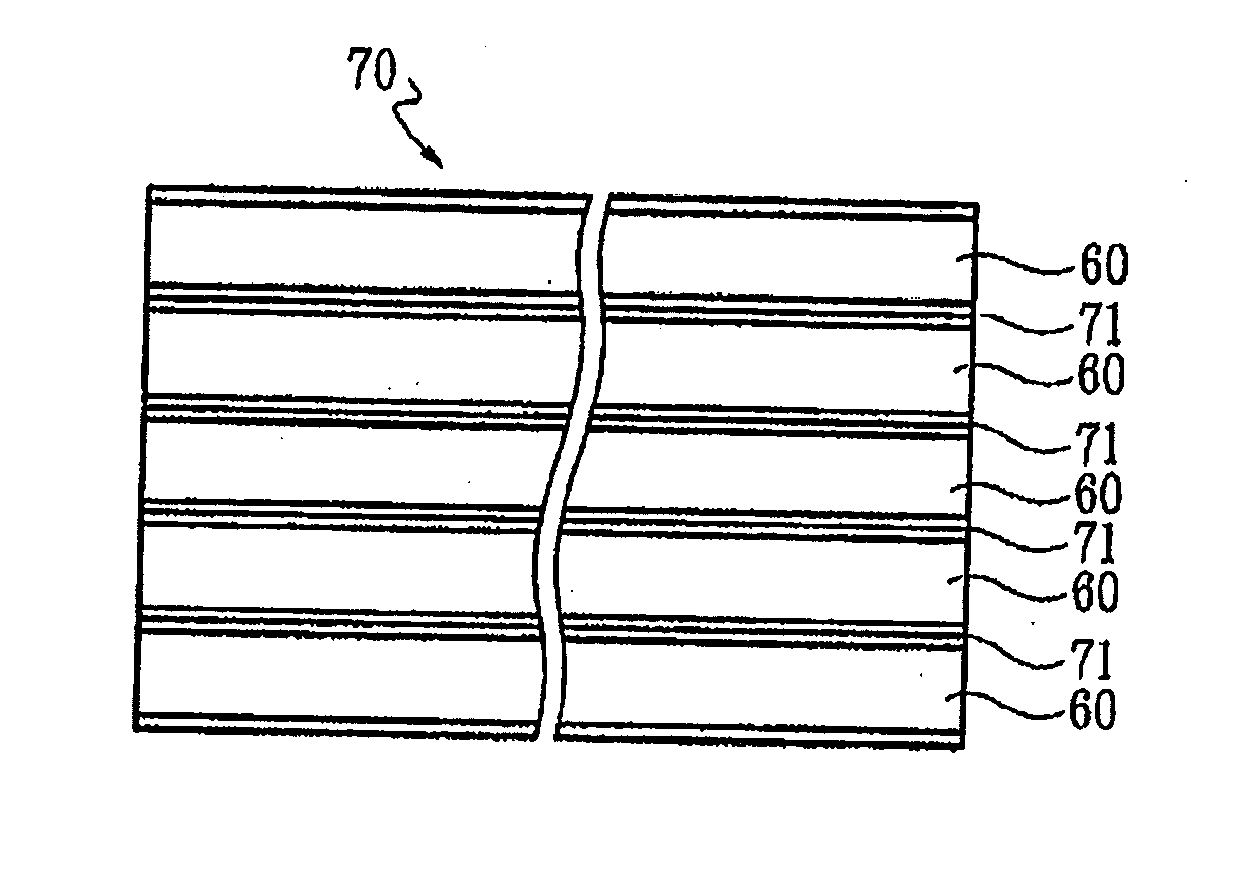
[0030]According to the boiler waterwall panel of the present invention (claim 3), since a seamless finned tube-web assembly, which is equivalent to the case in which a plurality of the aforementioned seamless finned single tubes are integrated into an entire continuous phase, then constitutes an entirety of the panel member, the transition portion ranging from the tubular portion to the fin portion is not required to be welded, too. Furthermore, the welding of the tip ends of the fin portions is not required. This eliminates the necessity of the welding operation at the time of producing the boiler waterwall panel. In a furnace housing using the boiler waterwall panels, damages of the fusion-bonded coating can be further remarkably reduced.
[0031]Accordingly, in the present invention (claim 3), not only the burden of the welding operation at the time of producing the boiler waterwall panel can be eliminated, but also in an improved operation rate of the boiler can be obtained, further remarkably.
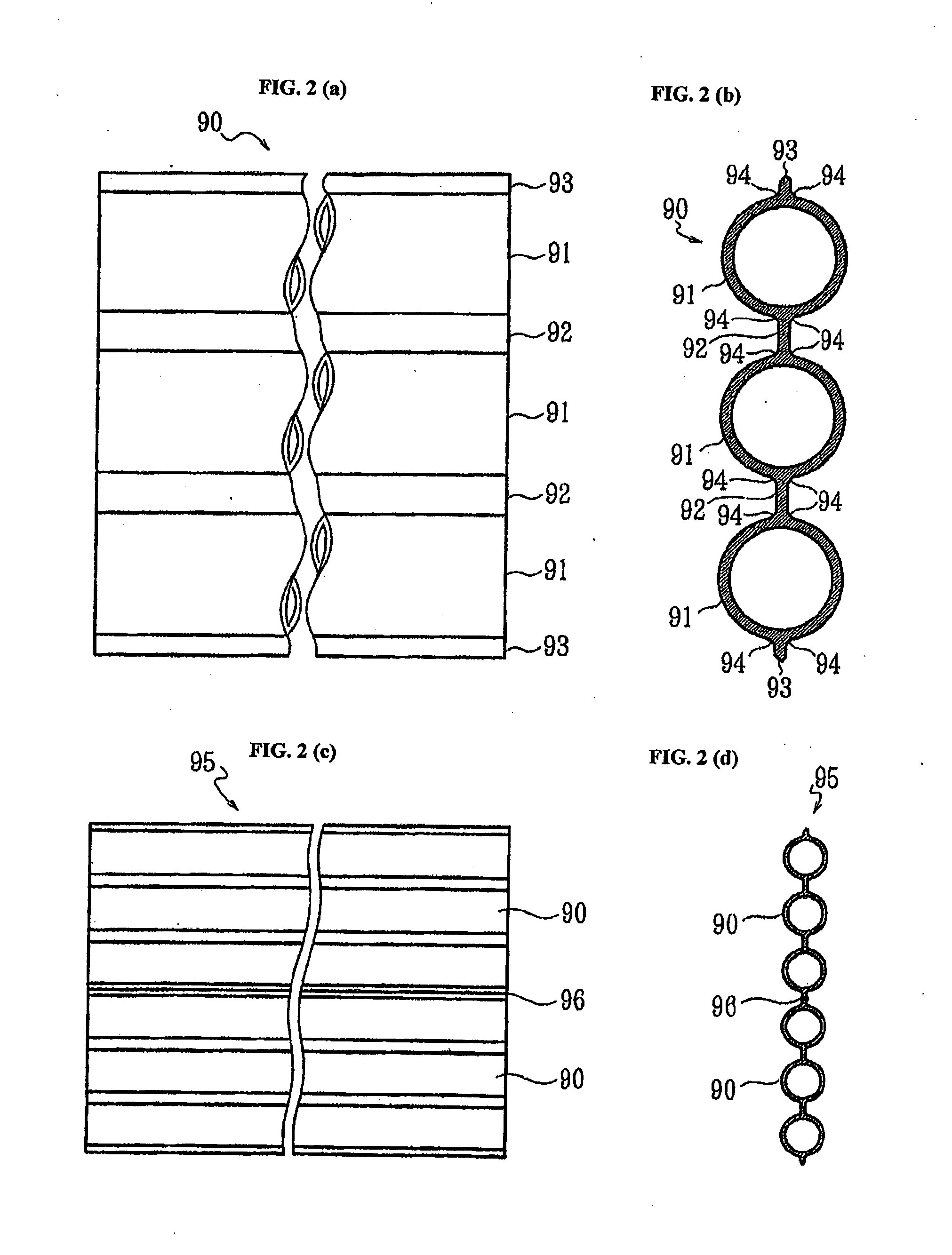
[0032]According to the boiler waterwall panel of the present invention (claim 4), since the external surface of the transition portion ranging from the tubular portion to the fin portion or the web portion in the panel member is formed into a concave surface, the stress concentration thereto can be reduced. Furthermore, since the cross-section of this portion has a configuration gradually increasing in thickness towards the basal portion, resulting in an enhanced rigidity of this portion, undesired effects by the stress due to the aforementioned steep temperature gradient can be reduced, which enhances the aforementioned preferable functions and results. Furthermore, the concave surface can be easily formed by a seamless forming method, such as e.g., a hot extrusion method, which in turn contributes a longer operating life of an extruding die for use in a hot extrusion method, etc.

Problems solved by technology

If the welding of the transition portion is not perfect, e.g., if there is any welding defect such as, e.g. pinholes, unevenness, blowholes, overlaps, undercuts, slag inclusions, weld cracks, sputters, and extremely uneven weld bead configurations, such welding defects become notches, resulting in a breakdown of the corrosion resistant alloy coating started from the welding defect.
As a result, corrosion of the subatrate material occurs at an early stage.
The repair of the found welding defects requires troublesome works, such as, e.g. blasting treatment and then TIG welding.
Furthermore, since the welding between the tubular member and the plate fin member is harder than the butt welding of the fin tip ends each other, welding defects tend to occur despite of spending much working hours, which bears a great burden of examination and repair of welding defects after the welding, as well as welding operation.

Method used


Image

  • Boiler waterwall panel
  • Boiler waterwall panel
  • Boiler waterwall panel

Examples


Embodiment Construction

[0069]The structure and production method of a boiler waterwall panel according to an embodiment of the present invention will be explained with reference to drawings. FIG. 1(a) is a side view of a finned tubular member 60, FIG. 1(b) is a cross-sectional view thereof, FIG. 1(c) is a side view of a panel body 70, FIG. 1(d) is a cross-sectional view thereof, FIG. 2(e) is a side view of a boiler waterwall panel 80, and FIG. 1(f) is a cross-sectional view thereof. The cross-section of each cross-sectional view denotes a cross-section perpendicular to the axial direction of the tubular portion 61.

[0070]This boiler waterwall panel 80 is produced as follows. That is, initially, a tubular member 60, which is a metal seamless finned pipe as the minimum constituent unit, is integrally produced by a hot extrusion method (see FIGS. 1(a) and 1(b)). A plurality of finned tubular members 60 are aligned in length, and the tip ends of the fin portions 62 as joining portions are welded with each othe...


PUM


Abstract

It is an object to reduce the burden of a welding operation in producing a boiler waterwall panel and to reduce the burden of maintaining a furnace housing using the boiler waterwall panels thereby to improve the operating rate of the boiler. In a boiler waterwall panel 80, a panel body 70 with water passages is constituted by a plurality of metal seamless finned single tubes 60 as constituent units integrally produced by a hot extrusion method, etc., and joined by welding tip ends of fin portions 62. On at least one surface side of the panel body 70, fusion-bonded coating 81 for frame-like edge portions and fusion-bonded coating 82 for inner region, of a corrosion resistant alloy are formed. The finned single tube 60 has a single tubular portion 61 for a cooling water passage and a pair of fin portions 62 extending in the tube axial direction at peripheral opposite sides of the tube, and the external surface of the transition portion 63 is formed into a concave surface having a curvature radius of 3 to 6 mm.

Description

TECHNICAL FIELD[0001]The present invention relates to a boiler waterwall panel constituting a furnace housing with cooling water passages.[0002]This boiler waterwall panel is a plate-pipe composite panel to be used as an element member at the time of forming a wall panel constituting a housing of a furnace (combustion chamber-cum-heat exchanger) as the core of a water heating boiler. A plurality of boiler waterwall panels are joined by welding vertically and horizontally to constitute a furnace housing.[0003]To improve the durability of the furnace housing inner surface, one surface of the boiler waterwall panel is covered with an alloy, e.g. a self-fluxing alloy of nickel series.BACKGROUND ART[0004]A method for heating a water-cooling panel segment comprising a metal tubular portion and a metal plate portion arranged alternately without causing heat strain is known (see e.g., Japanese Unexamined Laid-open Patent Publication No. 2000-329304). The structure and production method of t...

Claims


Application Information

Patent Timeline
Patent Type & Authority Applications(United States)
IPC IPC(8): F22B37/10
CPCF22B37/102F22B37/04F22B37/10
Inventor ITAI, KAZUNARITAKEYA, AKIHIROSOCHI, YOSHINOBUTANABE, MICHIOMATSUBARA, YOICHI
Owner DAI ICHI HIGH FREQUENCY
Why Eureka
Try Eureka