
Nanofunctional silica particles and manufacturing method thereof

Active Publication Date: 2010-12-09
NAKAMURA MICHIHIRO
View PDF6 Cites 10 Cited by
  • Summary
  • Abstract
  • Description
  • Claims
  • Application Information

AI Technical Summary

Benefits of technology

[0043]The nanofunctional silica particles and the manufacturing method thereof according to the present invention have unprecedented features and characteristics described below in connection with advantageous effects thereof.
[0044](a) The features of the nanofunctional silica particles are as follows:
[0045](1) The functional materials are located in the nanofunctional silica particles, in the inner layers thereof or in the core regions thereof, and the upper layers or outer layers of the organosilica compound can be morphologically distinguished from the shell regions. In other words, the structure of each of the silica particles can be roughly divided into the shell region and the core region.
[0046](2) The nanofunctional silica particles have functions that the contained functional materials have.
[0047](3) The nanofunctional silica particles can hold, in the surfaces thereof, and / or in the shells thereof, and / or in the cores thereof, the functional compound, which is a fluorescent colorant, a chemical agent or the like.
[0048](4) The particles are high in capability of adsorbing a protein, a nucleic acid or the like by acceptor groups in the surface layers or surfaces of the organosilica compound.

Problems solved by technology

However, surface layers of particles wherein this material, TEOS, is used are low in chemical reactivity, that is, in bonding capability to foreign proteins or nucleic acids; therefore, an attempt has been made for activating the particles by the introduction of an acceptor group by use of a silica compound different from the material TEOS (Patent Document 1).
However, these activated silica particles have a double structure composed of an inner shell made of TEOS and an outer shell or surface layer made of an acceptor group, and time, labor and other costs required for the manufacture thereof are high.
Moreover, the particles are not easily produced based on the selection of a silica compound wherein the number of bonding sites for forming silica network (Si—O), the number of which is four in TEOS, is three or less (such as MPS).
However, this technique gives high manufacturing costs, and has complicated manufacturing steps, and further requires considerable days for manufacturing the particles.
Additionally, the size (particle diameter) of the manufactured particles is not easily adjusted.
However, the method is not advantageous in a case where the particles aim for taking in a functional material, or in a case where the particles aim for being used in a quantitative experiment about DNA, a protein or the like.
Another reason therefor appears to be as follows: about particles having many pores as in Patent Document 2, the effective adhesive area thereof, to which DNA or a protein can adhere, does not depend only on the surface area based on the diameters of the particles, and is varied in accordance with the size or the number of the pores, or the positions thereof, thus, the parameter of the adhesive area is diversified so that a problem is caused for quantitation.
For example, a magnetic material is used as an imaging agent in an MRI; however, the material is not usually used in any detailed observation with a microscope.
However, through the existing imaging agent, macro-observation can be attained, but micro-observation, wherein a microscope is used, cannot be attained.
Additionally, a fluorescently labeled antibody used in observation with a microscope cannot be observed through a CT or an MRI.
However, the particles have a technical problem.
Thus, the particles have not yet been completed.

Method used


Image

  • Nanofunctional silica particles and manufacturing method thereof
  • Nanofunctional silica particles and manufacturing method thereof
  • Nanofunctional silica particles and manufacturing method thereof

Examples


example 1

100 nm Gold Colloid Coated with a 20 nm or Less MPS Layer

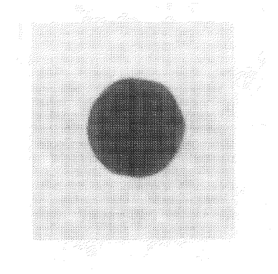
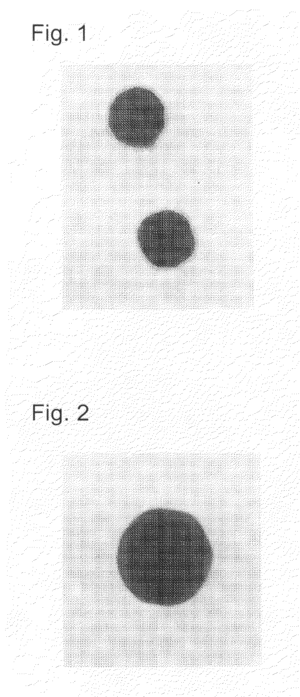
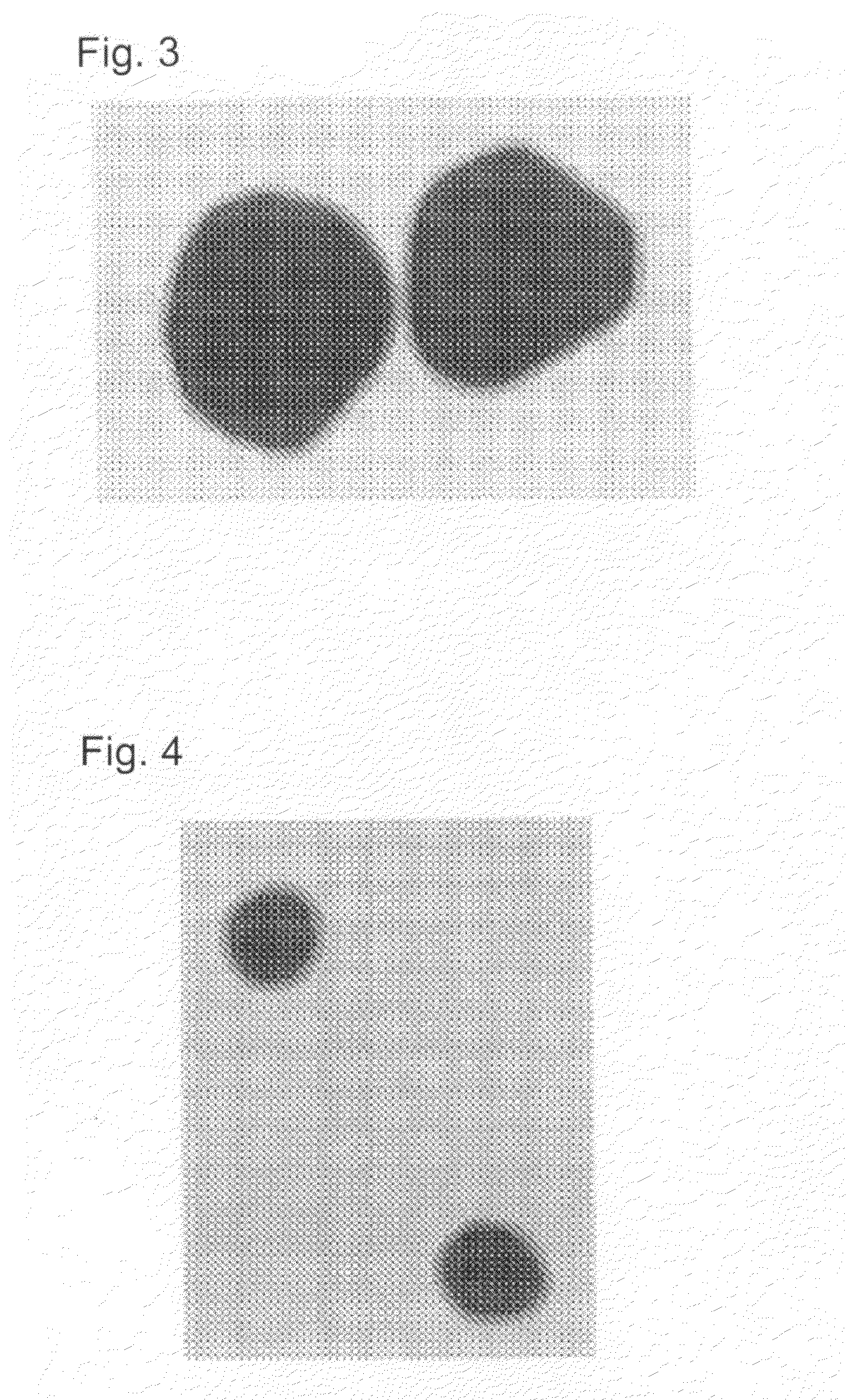
[0109]To 90 μL of a 100 nm gold colloid (manufactured by Tanaka Kikinzoku Kogyo K.K.) were each added 100 μL of MPS diluted 500 times and 810 μL of a 28% by weight aqueous ammonia solution, and the components were mixed with one another. The reactive components were then allowed to react with one another at 100° C. for 3 hours. Next, the reaction finished liquid was subjected to a high-speed centrifugal separator (at 10,000×g for 5 minutes). Pellets thereof were then collected. The resultant pellets were repeatedly washed by centrifugation totally 6 times, using 70% by volume ethanol and distilled water alternately three times, respectively. Next, the washed pellets were stirred in an ultrasonic crusher, and then sampled to be observed with an electron microscope. As a result, a 20 nm or less MPS layer coat was recognized. The control ratio of the thicknesses of the shells was about 15%.

example 2

100 nm Gold Colloid Coated with a 10 nm or Less MPS Layer

[0110]To 85 μL of a 100 nm gold colloid (manufactured by Tanaka Kikinzoku Kogyo K.K.) were each added 50 μl of MPS diluted 500 times and 865 μL of a 28% by weight aqueous ammonia solution, and the components were mixed with one another. The reactive components were then allowed to react with one another at 100° C. for 3 hours. Next, the reaction finished liquid was subjected to a high-speed centrifugal separator (at 10,000×g for 5 minutes). Pellets thereof were then collected. The resultant pellets were repeatedly washed by centrifugation totally 6 times, using 70% by volume ethanol and distilled water alternately three times, respectively. Next, the washed pellets were stirred in an ultrasonic crusher, and then sampled to be observed with an electron microscope. As a result, a 10 nm or less MPS layer coat was recognized. The control ratio of the thicknesses of the shells was about 30%.

example 3

250 nm Gold Colloid Coated with a 30 nm or Less MPS Layer

[0111]To 500 μL of a 250 nm gold colloid (manufactured by BB International) were each added 100 μL of MPS diluted 500 times and 450 μL of a 28% by weight aqueous ammonia solution, and the components were mixed with one another. The reactive components were then allowed to react with one another at 100° C. for 3 hours. Next, the reaction finished liquid was subjected to a high-speed centrifugal separator (at 10,000×g for 5 minutes). Pellets thereof were then collected. The resultant pellets were repeatedly washed by centrifugation totally 6 times, using 70% by volume ethanol and distilled water alternately three times, respectively. Next, the washed pellets were stirred in an ultrasonic crusher, and then sampled to be observed with an electron microscope. As a result, a 30 nm or less MPS layer coat was recognized. The control ratio of the thicknesses of the shells was about 16.


PUM

PropertyMeasurementUnit
Temperatureaaaaaaaaaa
Fractionaaaaaaaaaa
Nanoscale particle sizeaaaaaaaaaa

Abstract

Provided are nanofunctional silica particles having excellent functionality and quality, and capable of being mass-produced at low costs. According to the present invention, there are provided nanofunctional silica particles including a coating layer containing one or more silica compounds selected from the group consisting of mercaptopropyl trimethoxysilane (MPS), mercaptopropyl triethoxysilane (MPES), mercaptopropyl methyldimethoxysilane (MPDMS), trimethoxy[2-(7-oxabicyclo[4.1.0]-hept-3-yl)ethyl]silane (EpoPS), thiocyanatopropyl triethoxysilane (TCPS), acryloxypropyl trimethoxysilane (ACPS), and aminopropyl trimethoxysilane (APS); and functional particles in the coating layer, and being used in imaging, assay, diagnosis, treatment or the like, medicine or bioresearch.

Description

TECHNICAL FIELD [0001]This invention relates to silica nanoparticles having a double structure wherein the nanoparticle is roughly divided into a region of an outer layer or shell occupying a surface layer and a region of an inner layer or core occupying a layer beneath the surface layer, and in particular relates to a method for manufacturing novel silica nanoparticles that exhibit multifunctionality, and a usage thereof. More specifically, the present invention relates to nanofunctional silica particles which have remarkably better characteristics than conventional silica particles, contain a functional material in the surface thereof, and / or the shell region thereof, and / or the core region thereof, and have a nature of the functional material together. Moreover, a manufacture of the nanofunctional silica particles is also disclosed.BACKGROUND ART [0002]Various kinds of techniques about a method for manufacturing silica particles or silica spheres, and a usage thereof have been re...

Claims


Application Information

Patent Timeline
IPC IPC(8): B32B5/00A61K49/00H01F1/00
CPCA61K9/1676C08G77/06Y10T428/2995C08G77/26C08G77/28C08G77/20A61P43/00
Inventor NAKAMURA, MICHIHIRO
Owner NAKAMURA MICHIHIRO
Learn More