
Gas liquid contactor and effluent cleaning system and method

a technology of contactor and effluent, which is applied in the direction of gaseous fuel, separation process, transportation and packaging, etc., can solve the problems of limited control of concentration gradient, prone to clogging and breakage, and serious clogging problems, and achieves low pressure sorbent operation, small size, and large volumetric mass transport coefficient

Inactive Publication Date: 2010-12-23
NEUMANN SYST GROUP
View PDF37 Cites 23 Cited by
  • Summary
  • Abstract
  • Description
  • Claims
  • Application Information

AI Technical Summary

Benefits of technology

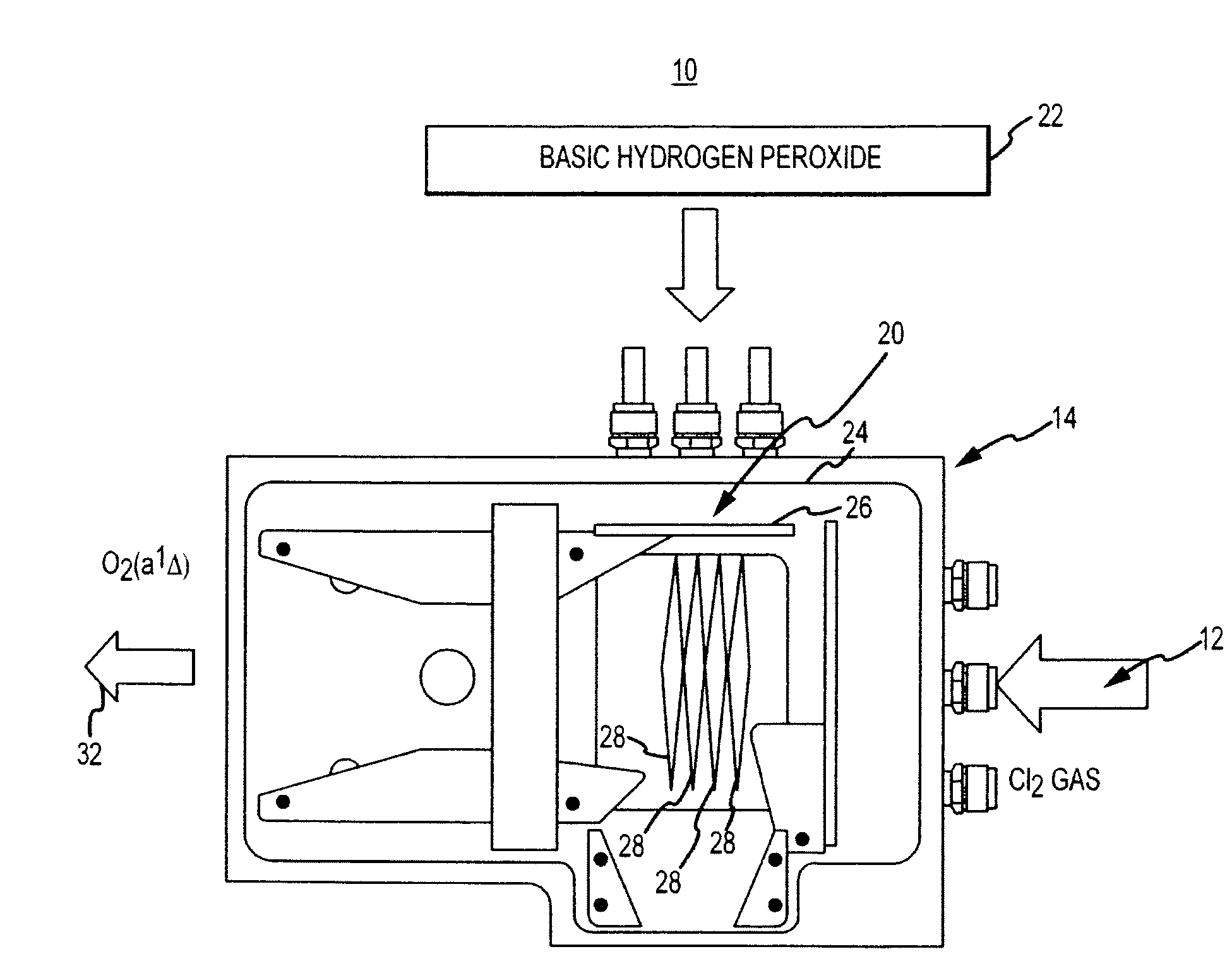
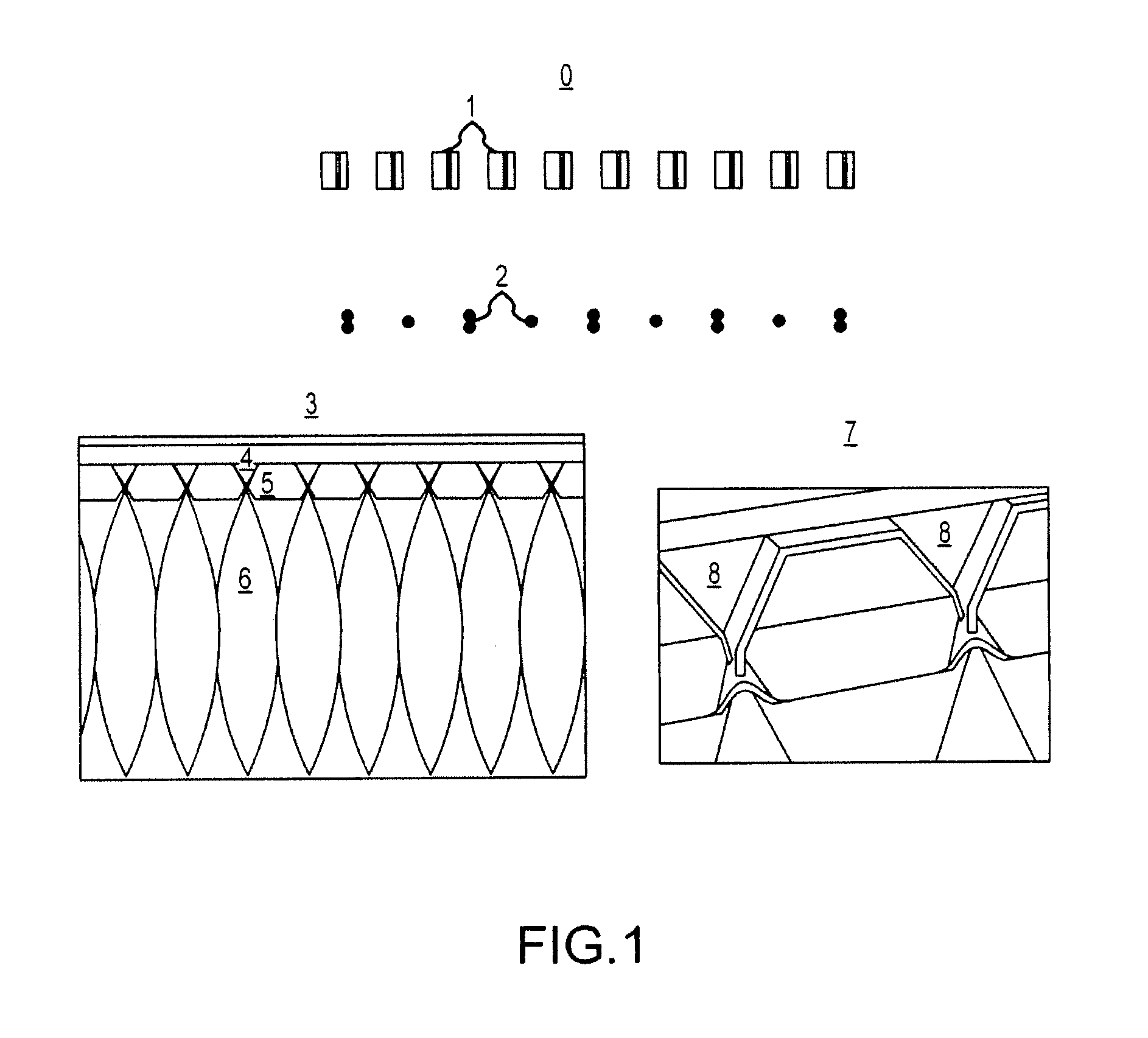
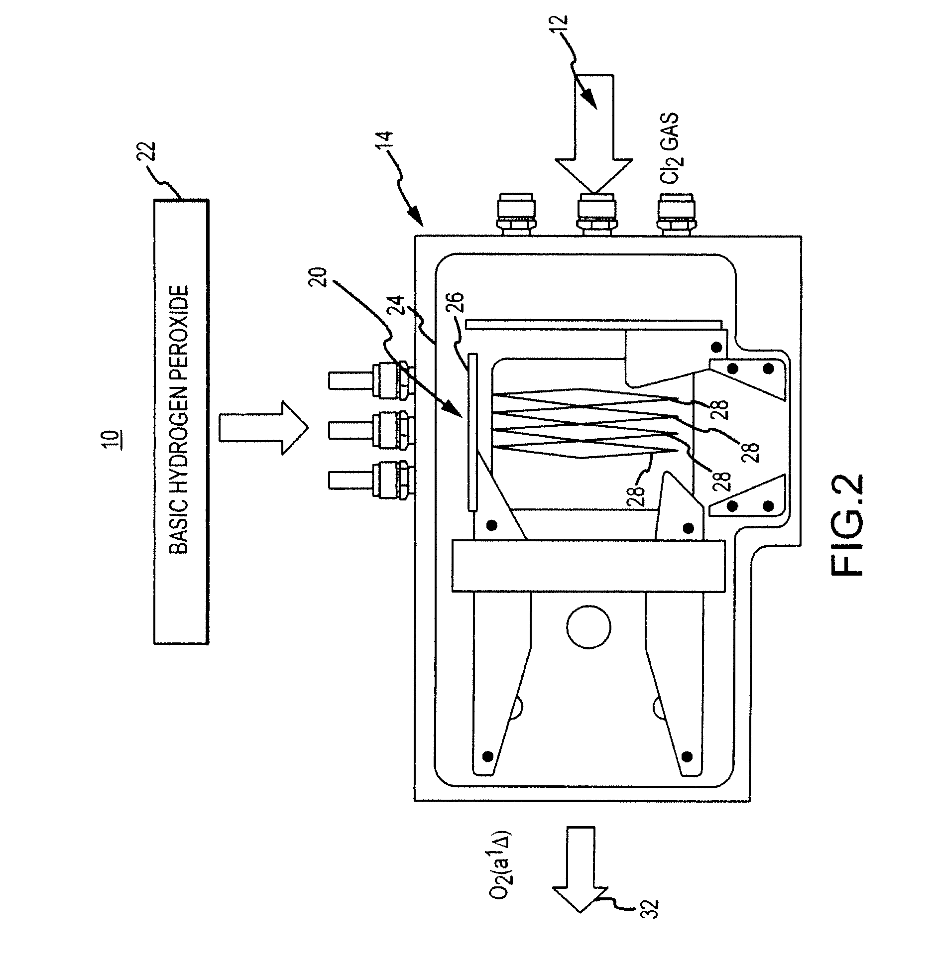
"The invention is a gas liquid contactor and effluent cleaning system that solves problems in existing technologies. It has large volumetric mass transport coefficients, requires minimal pumping capability, and uses enhanced specific surface area of a flat jet to improve gas liquid reactors. The system includes a reaction chamber, gas inlet, gas outlet, and a liquid plenum coupled to the reaction chamber. A nozzle array is configured to provide mass transfer interaction with the gas phase molecule. The gas liquid contactor system is modular, compact, and has high specific surface area, uniform jet velocity, and low clogging and gas flow disruption. The invention also provides a method of processing gas phase molecules using the gas liquid contactor system."

Problems solved by technology

In many gas liquid reaction systems the solubility of the CL* is very low and control of the concentration gradient, therefore, is limited.
Smaller and more densely packed jets improve the specific surface area, but are prone to clogging and breakup.
Clogging is a serious problem since the reaction between chlorine and basic hydrogen peroxide produces chlorine salts of the alkali metal hydroxide used to make the basic hydrogen peroxide.
Clogging also limits the molarity range of the basic hydrogen peroxide, which reduces singlet oxygen yield and laser power.
Problems inherent in producing the fuel increase the weight and decrease the efficiency of the COIL laser as a whole.
Another downside of standard countercurrent, gravitational or aerosol / droplet gas liquid contactors is that gas flows must be at a low enough velocity such that gravity effects are greater than the buoyancy of the droplets.

Method used


Image

  • Gas liquid contactor and effluent cleaning system and method
  • Gas liquid contactor and effluent cleaning system and method
  • Gas liquid contactor and effluent cleaning system and method

Examples


Embodiment Construction

[0106]The invention relates to a gas liquid contactor and effluent cleaning system and method and more particularly to an array of nozzles configured to produce uniformly spaced flat liquid jets shaped to minimize disruption from a gas. Moreover, various embodiments directly provide a plurality of small single unit processes, aggregated into modules, which, by their design, overcome the shortcomings of conventional designs. Modularizing single unit processes allows for small systems which may be scaled by simply multiplying the module by convenient integers to accommodate the scale of the process.

[0107]Moreover, a single gas liquid contactor capable of producing a thin flat liquid jet can be readily multiplied and aggregated into a module or modules that perform within a range of gas flow rates in a very compact design, dramatically smaller than a conventional countercurrent reactor for an equivalent reaction yield. This aggregation into a module or modules may be conducted serially...


PUM

PropertyMeasurementUnit
pressureaaaaaaaaaa
widthaaaaaaaaaa
widthaaaaaaaaaa

Abstract

The invention relates to a gas liquid contactor and effluent cleaning system and method and more particularly to an array of nozzles configured to produce uniformly spaced flat liquid jets shaped to minimize disruption from a gas. An embodiment of the invention is directed towards a gas liquid contactor module including a liquid inlet and outlet and a gas inlet and outlet. An array of nozzles is in communication with the liquid inlet and the gas inlet. The array of nozzles is configured to produce uniformly spaced flat liquid jets shaped to minimize disruption from a gas flow and maximize gas flow and liquid flow interactions while rapidly replenishing the liquid.

Description

[0001]This application is a continuation-in-part of application Ser. No. 12 / 012,568, entitled “Two Phase Reactor,” filed on Feb. 4, 2008, which is a continuation of U.S. patent application Ser. No. 11 / 057,539, entitled “Two Phase Reactor,” filed on Feb. 14, 2005, now U.S. Pat. No. 7,379,487, which claims the benefit of U.S. Provisional Application No. 61 / 100,564, entitled “System for Gaseous Pollutant Removal,” filed on Sep. 26, 2008, U.S. Provisional Application No. 61 / 100,606, entitled “Liquid Gas Contactor System and Method,” filed on Sep. 26, 2008, and U.S. Provisional Application No. 61 / 100,591, entitled “Liquid Gas Contactor and Effluent Cleaning System and Method,” filed on Sep. 26, 2008; all of the disclosures set-forth above are herein specifically incorporated in their entireties by this reference.BACKGROUND OF THE INVENTION[0002]1. Field of the Invention[0003]The invention relates to a gas liquid contactor and effluent cleaning system and method and more particularly to a...

Claims


Application Information

Patent Timeline
Patent Type & Authority Applications(United States)
IPC IPC(8): B01D53/18
CPCB01D53/1475Y02C10/06B01D53/18B01D53/62B01D53/78B01D2251/106B01D2251/2065B01D2251/30B01D2251/40B01D2251/402B01D2251/404B01D2251/502B01D2251/80B01D2252/20447B01D2257/302B01D2257/304B01D2257/404B01D2257/406B01D2257/504B01D2257/602B01D2259/124B01D2259/126C10L3/10C10L3/102H01S3/095H01S3/2215Y02C10/04B01D53/1493Y02C20/40B01D53/1456B01D53/1462B01D53/1468B01J10/00B01F25/30B01D53/77
Inventor NEUMANN, DAVID KURTMILLER, NICHOLAS J.NIZAMOV, BORIS R.HENSHAW, THOMAS LEEAWTRY, ANDREW R.BRASSEUR, JASON K.HOBBS, KEITH R.TOBIAS, JASON A.MCDERMOTT, WILLIAM E.
Owner NEUMANN SYST GROUP
Learn More