Planar optical waveguide element, chromatic dispersion compensator, optical filter, optical resonator and methods for designing the element, chromatic dispersion compensator, optical filter and optical resonator

Inactive Publication Date: 2010-12-23
THE FUJIKURA CABLE WORKS LTD
View PDF17 Cites 25 Cited by
  • Summary
  • Abstract
  • Description
  • Claims
  • Application Information

AI Technical Summary

Benefits of technology

[0036]According to the exemplary aspect described in (1) above, because the mode field diameter of the fundamental mode expands, it is possible to inhibit the effects (i.e., scattering loss) on the optical characteristics from roughness of the core-side walls which are formed from a high refractive index material, in which the roughness is unavoidably generated in the manufacturing process.
[0037]According to the exemplary aspect described in (2) above, a planar optical waveguide element having a Bragg grating pattern can reduce the polarization dependence of the optical characteristics.
[0038]According to the exemplary aspect described in (3) above, it is possible to make the waveguide length shorter than a sampled grating.
[0039]According to the exemplary aspect described in (4) above, compared to a related art chirped grating in which the pitch changes gradually, tolerance control in the manu

Problems solved by technology

However, in the fiber Bragg grating, because there are limits to the range over which the refractive index can be changed in order to manufacture a grating pattern, an operation in which the aforementioned spectrum characteristics are apodized by applying an inverse Fourier transform is also carried out so that these limits are not exceeded.
On the other hand, measures to deal with (U) have the problems that, because the transmission line becomes more complex as the number of optical components increases, they lead to increased size, increased complexity, and increased costs for the optical communication equipment.
Solving the above described problems is difficult using conventional technology.
Accordingly, it is not possible for the technology of this document to be applied to the design of chromatic dispersion compensators that are formed from high refractive index optical waveguides in which the polarization dependence on the substrate has been reduced.
Accordingly, the removal of interference between wavelength channels has not been considered in this design method, therefore the problem arises that the chromatic dispersion characteristics are deteriorated by the interference between wavelength channels.
However, this is not possible in the design method of Patent document 1.
Accordingly, it is not possible for the technology of this document to be applied to the design of chromatic dispersion compensators that are formed from high refractive index optical waveguides in which the polarization dependence on a substrate is reduced.
Accordingly, the technology of Patent document

Method used


Image

  • Planar optical waveguide element, chromatic dispersion compensator, optical filter, optical resonator and methods for designing the element, chromatic dispersion compensator, optical filter and optical resonator
  • Planar optical waveguide element, chromatic dispersion compensator, optical filter, optical resonator and methods for designing the element, chromatic dispersion compensator, optical filter and optical resonator
  • Planar optical waveguide element, chromatic dispersion compensator, optical filter, optical resonator and methods for designing the element, chromatic dispersion compensator, optical filter and optical resonator

Examples


reference example 1

[Reference Example 1 of a Chromatic Dispersion Compensator]

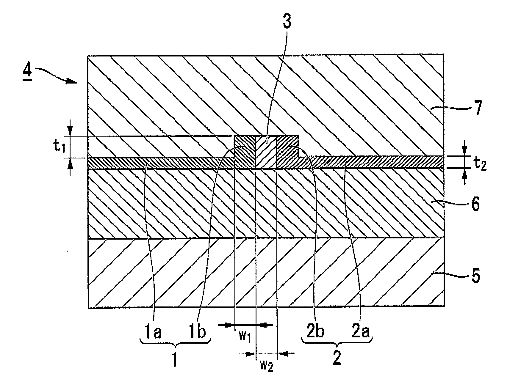
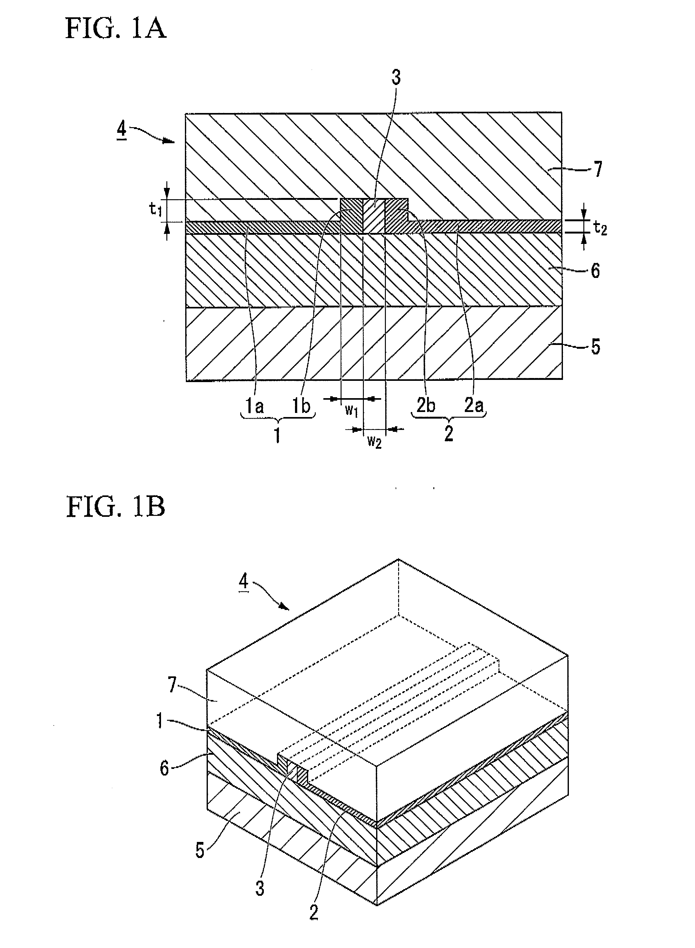
[0224]In the present reference example, a case was calculated as Reference example 1 relating to a chromatic dispersion compensator in which, in an optical waveguide structure having the composite core shown in FIG. 15 (having no center gap), the first and second ribs 31 and 32 were formed from Si, the outer side core 34 was formed from SixNy, the substrate 35 was formed from Si, the bottom cladding 36 was formed from SiO2, the top cladding 37 was formed from SiO2, and in which t1=250 nm, t2=50 nm, w1=100 nm, w2=160 nm, tout=600 nm, and tin=100 nm, and in which the thickness of the bottom cladding 36 was 2000 nm, and the maximum thickness of the top cladding 37 was 2000 nm.

[0225]In this Reference example 1 as well, in the same way as in Example 1, changes in wout and win relative to the effective refractive index were calculated in accordance with Step [1]. The results thereof are shown in FIG. 16. In this Reference example ...

example 2

[Example 2 of an Optical Filter]

[0277]The present example is an example of the design of a beam splitter having a power reflectance of approximately 40%. A beam splitter can be used in applications to split the signal light of each channel into two paths.

[0278]The design method of this beam splitter is performed in the same way as that performed for the optical filter of Example 1, other than the power reflectance parameters being altered.

[0279]The design steps of the present example as well comprise four steps in the same way as in Example 1. The same correspondence relationship between the effective refractive index and win and wout in Step [1] as that of Example 1 is used here. In Step [2], the absolute value of the field reflectance is set to 0.64 (i.e. 64%) such that the power reflectance within the reflection band of each channel, becomes 0.4 (40%). The chromatic dispersion in the reflection band of each channel is set to zero. The optical characteristics specified for the opt...

example 3

[Example 3 of an Optical Filter]

[0281]The present example is an example of the design of an optical filter having a single reflection band. The design steps are the same as in Examples 1 and 2. The power reflectance of the reflection band is set to approximately 90%. The correspondence relationship between the effective refractive index and win and wout is identical to Examples 1 and 2. The specified optical characteristics are shown in FIG. 36. The spectrum width of the reflection band is 0.01 THz.

[0282]The effective refractive index distribution derived based on the inverse scattering problem solution using these optical characteristics is shown in FIG. 37 and FIG. 38. The results obtained when the effective refractive index is converted to a square-like shaped profile are shown in FIG. 39. The optical filter of the present example can be used to extract signal light of a single specific channel as reflected light.

[0283]Note that the spectrum width of the reflection band is not li...


PUM


Abstract

There is provided a planar optical waveguide element in which an optical waveguide comprises a core, and a gap portion that is positioned in a center of a width direction of the core so as to extend in a propagation direction of guided light, and that has a lower refractive index than that of the core; and wherein the core comprises two areas that are separated by the gap portion, and a single mode optical waveguide, in which a single mode is propagated span crossing these two areas, is formed.

Description

CROSS-REFERENCE TO RELATED APPLICATION[0001]This is a Continuation Application of International Application No. PCT / JP2009 / 053763, filed on Feb. 27, 2009, which claims priority to Japanese Patent Application No. 2008-051346, filed Feb. 29, 2008. The contents of the aforementioned applications are incorporated herein by reference.TECHNICAL FIELD[0002]Apparatuses and embodiments described herein related to a planar optical waveguide element and design method thereof, in which the planar optical waveguide element can be used in various applications such as a chromatic dispersion compensator, an optical filter and an optical resonator and the like.BACKGROUND ART[0003]The following are examples of chromatic dispersion compensation in an optical waveguide structure for which polarization dependence is not considered.[0004]An element having a plurality of Bragg grating elements in which the period changes spatially such that chromatic dispersion is compensated in a plurality of wavelength ...

Claims


Application Information

Patent Timeline
IPC IPC(8): G02B6/34G06F17/10
CPCG02B6/124G02B6/10G02B6/29394G02B6/29325
Inventor OGAWA, KENSUKEGUAN, NINGSAKUMA, KEN
Owner THE FUJIKURA CABLE WORKS LTD
Why Eureka
Try Eureka