Plasma display panel

a technology of display panels and plasma, applied in the direction of gas-filled discharge tubes, gas mixture absorption, electrodes, etc., can solve the problems of defective lighting, degrading video quality, and causing greater “discharge delay”, so as to enhance the second electron emission characteristics of the protective layer, boost the brightness, and reduce the effect of discharge delay

Inactive Publication Date: 2010-12-30
PANASONIC CORP
View PDF15 Cites 2 Cited by
  • Summary
  • Abstract
  • Description
  • Claims
  • Application Information

AI Technical Summary

Benefits of technology

[0023]According to such configuration, the secondary electron emission characteristics in the protective layer are enhanced so that low voltage drive can be realized even if the partial pressure of the Xe gas of the discharge gas is increased to boost the brightness. A PDP that enables stable discharging can be realized by suppressing the absorption of impurity gas to the protective layer.
[0024]Furthermore, the aggregated particle formed by aggregating multiple crystal particles of magnesium oxide is desirably attached to the protective layer

Problems solved by technology

As a result, a defective lighting occurs and flickers which degrade a video quality are produced.
However, a greater discharge voltage invites a greater “discharge delay”, thereby incurring a defective lighting which degrades a video quality.
In the protective layer containing material other than MgO, the amount of impurity gas

Method used


Image

  • Plasma display panel
  • Plasma display panel
  • Plasma display panel

Examples


Embodiment Construction

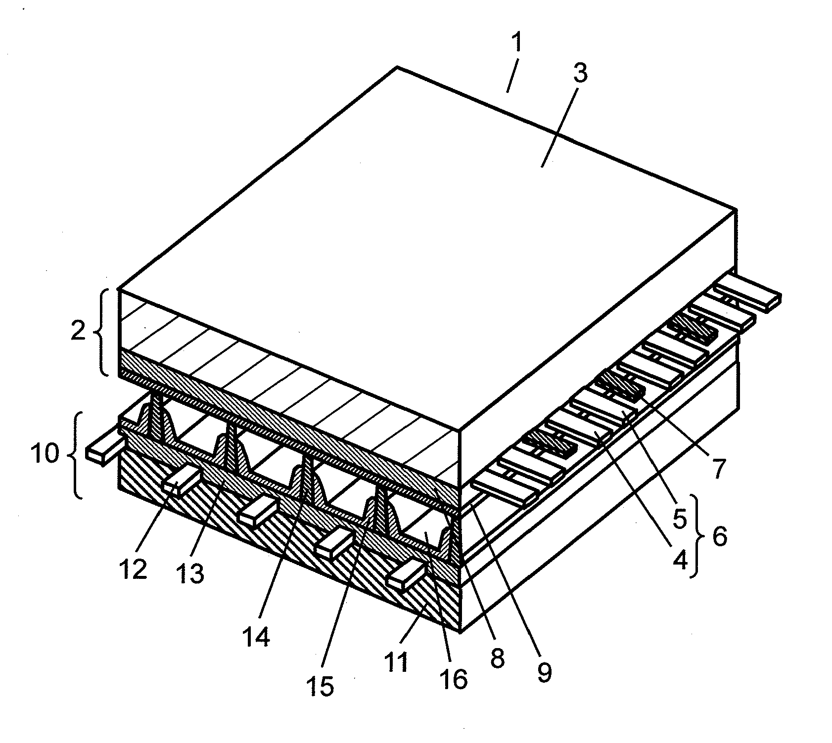
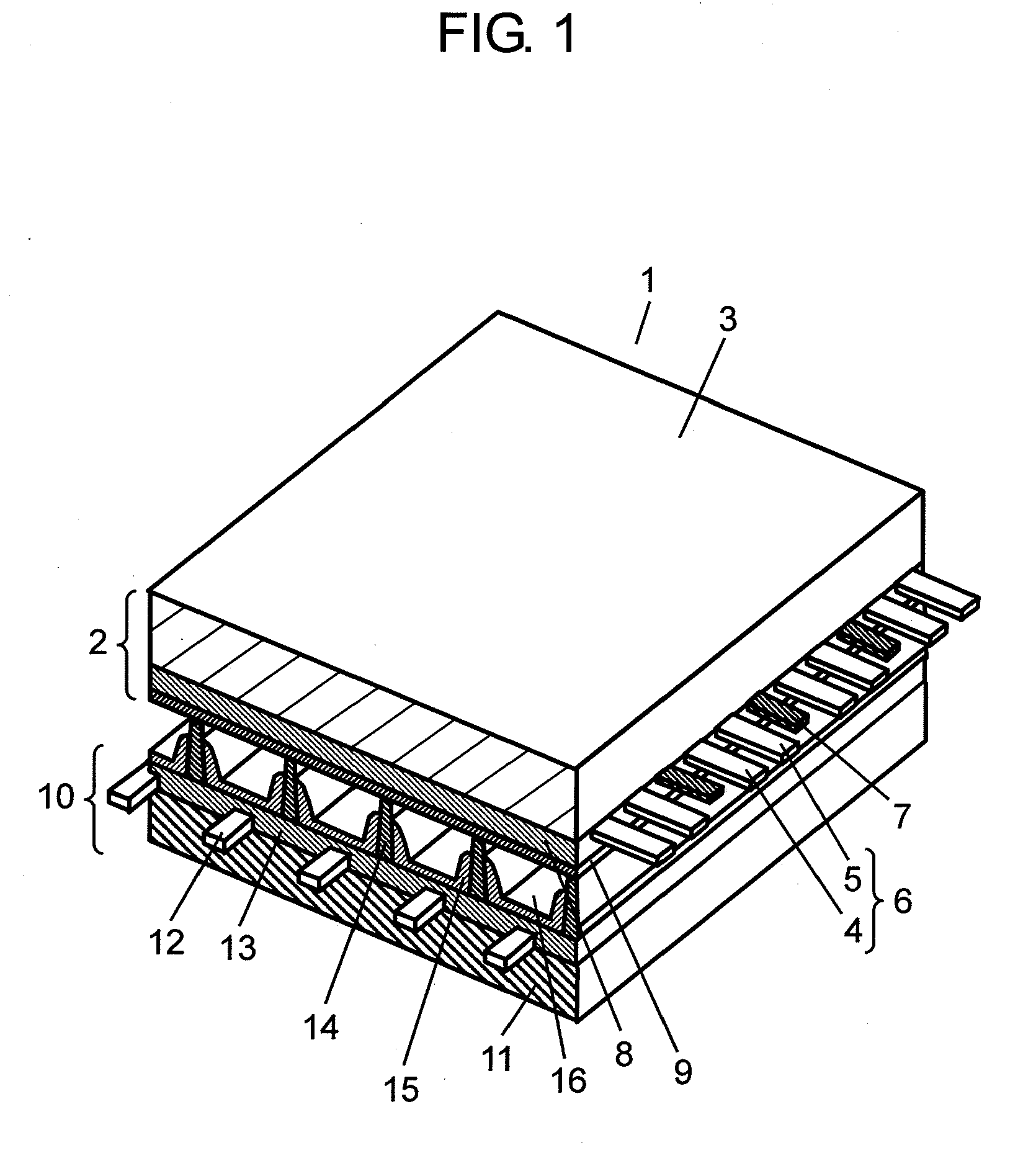
[0034]FIG. 1 shows a perspective view illustrating a structure of PDP 1 in accordance with the embodiment of the present invention. PDP 1 is basically structured similarly to a PDP of AC surface discharge type generally used. As shown in FIG. 1, PDP 1 is formed of a first substrate (hereinafter referred to as front panel 2) including front glass substrate 3, and a second substrate (hereinafter referred to as rear panel 10) including rear glass substrate 11, which panels confront each other and the peripheries are air tightly sealed with sealing agent such as glass frit. which is filled with discharge gas such as neon (Ne) and xenon (Xe) at a pressure falling within a range between 400 Torr and 600 Torr (between 53300 Pa and 80000 Pa).

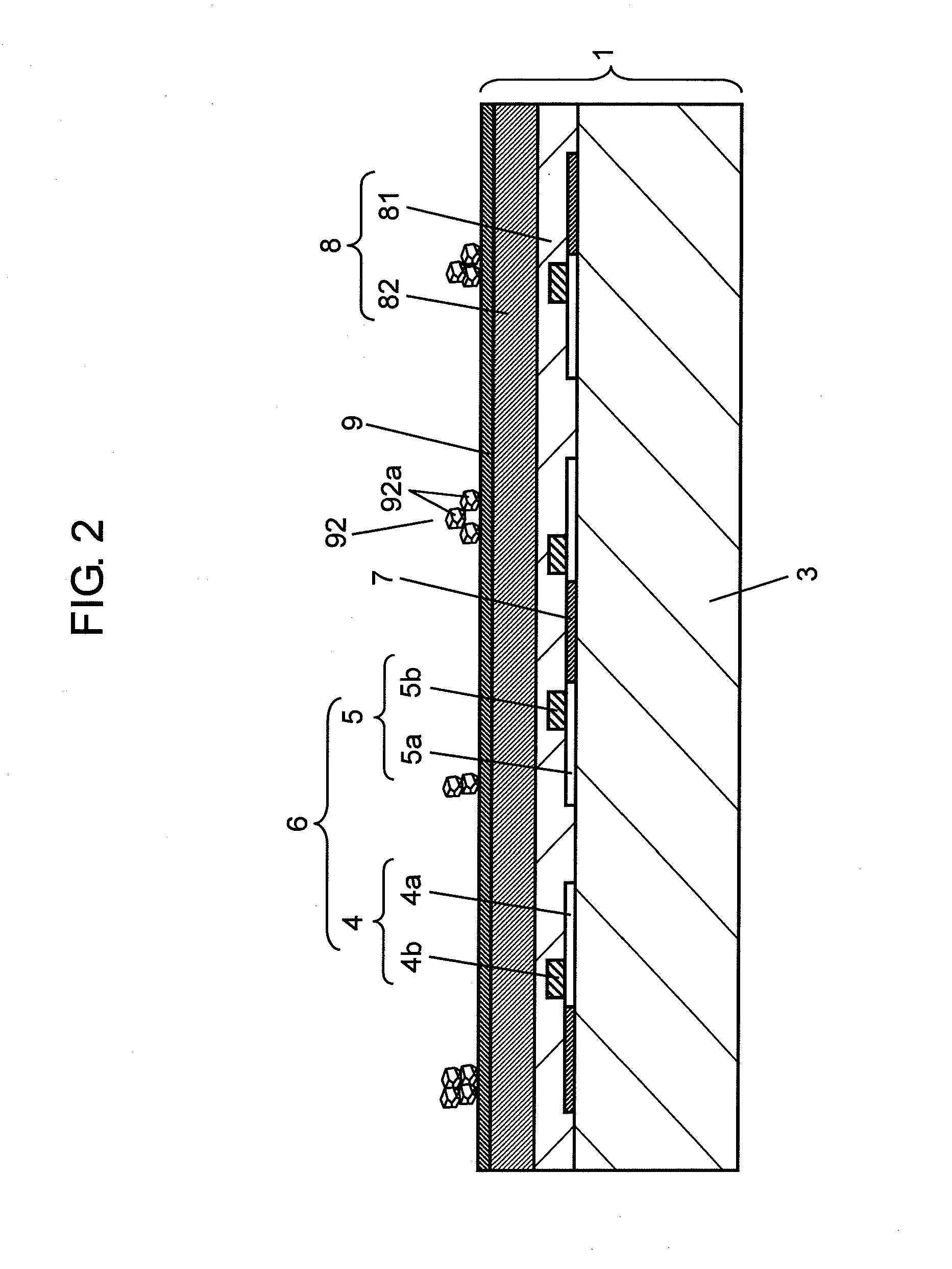
[0035]Multiple pairs of belt-like display electrodes 6, each of which are formed of scan electrode 4 and sustain electrode 5, are placed in parallel with multiple black stripes (lightproof layers) 7 on front glass substrate 3 of front panel 2. Dielectri...


PUM


Abstract

A PDP includes a front panel including display electrode (6) formed on glass substrate (3), dielectric layer (8) covering display electrode (6), and protective layer (9) formed on dielectric layer (8); and a rear panel opposing to the front panel to form a discharge space filled with discharge gas, and including an address electrode formed along a direction intersecting with display electrode (6), and a barrier rib partitioning the discharge space, wherein protective layer (9) is formed of a metal oxide made of magnesium oxide and calcium oxide and contains aluminum, and a diffraction angle where a peak of the metal oxide occurs exists between a diffraction angle where a peak of the magnesium oxide occurs and a diffraction angle where a peak of the calcium oxide occurs in an X-ray diffraction analysis on a surface of protective layer (9).

Description

TECHNICAL FIELD[0001]The present invention relates to plasma display panels to be used in display devices.BACKGROUND ART[0002]A plasma display panel (hereinafter referred to simply as a PDP) allows achieving a high definition display and a large-size screen, so that television receivers (TV) with large screens of as large as 100 inches diagonal length can be commercialized by using the PDP. In recent years, use of the PDPs in high-definition TVs, which need more than doubled scanning lines than conventional NTSC method, has progressed. The PDP has been demanded to further reduce the power consumption in order to meet the energy-saving trend, and the PDP free from lead (Pb) has been also required in order to contribute to environment protection.[0003]The PDP is basically formed of a front panel and a rear panel. The front panel is configured by a glass substrate made of sodium-borosilicate-based float glass; display electrodes, formed of striped transparent electrodes and bus electro...

Claims


Application Information

Patent Timeline
IPC IPC(8): H01J17/49H01J11/12H01J11/22H01J11/24H01J11/26H01J11/34H01J11/40H01J11/52
CPCH01J11/40H01J11/12
Inventor HASHIMOTO, JUNGOTOU, MASASHITAKEDA, EIJISHIMAMURA, TAKAYUKI
Owner PANASONIC CORP
Why Eureka
Try Eureka