Electrode catalyst substrate and method for producing the same, and polymer electrolyte fuel cell

a technology of electrolyte fuel cell and electrode catalyst, which is applied in the direction of cell components, electrochemical generators, nuclear engineering, etc., can solve the problems of limited improvement in the utilization rate of catalyst particles, and achieve the effect of improving the output of the fuel cell

Active Publication Date: 2010-12-30
TOYOTA JIDOSHA KK +1
View PDF6 Cites 14 Cited by
  • Summary
  • Abstract
  • Description
  • Claims
  • Application Information

AI Technical Summary

Benefits of technology

[0023]A porous carbon film is hydrophilized and then the hydrophilized film is immersed in a solution containing catalytic metal ions, so that the porous carbon film can be entirely impregnated with the solution. After this, a reducing agent is added to the solution and then catalytic metal ions are reduced, so that catalyst particles can be loaded onto the surface of the porous carbon film in a fine and highly dispersed manner. This may be because hydrophilic groups introduced onto the surface of the porous carbon film function as nuclei for the precipitation of catalyst particles. In the thus obtained electrode catalyst, catalyst particles are loaded in a highly dispersed manner along the gas diffusion pathway. Hence, the output of the fuel cell can be improved using the electrode catalyst for anodes and / or cathodes of fuel cells.

Problems solved by technology

However, when noble metal particles are loaded onto a powdered porous carrier, the noble metal particles are not always loaded onto the carrier surface, but may be loaded inside the porous carrier away from the surface.
Therefore, improvement in the dispersibility of a noble metal particle-loaded carrier alone can cause a limited improvement in utilization rate of catalyst particles.

Method used


Image

  • Electrode catalyst substrate and method for producing the same, and polymer electrolyte fuel cell
  • Electrode catalyst substrate and method for producing the same, and polymer electrolyte fuel cell
  • Electrode catalyst substrate and method for producing the same, and polymer electrolyte fuel cell

Examples


example 1

1. Preparation of Sample

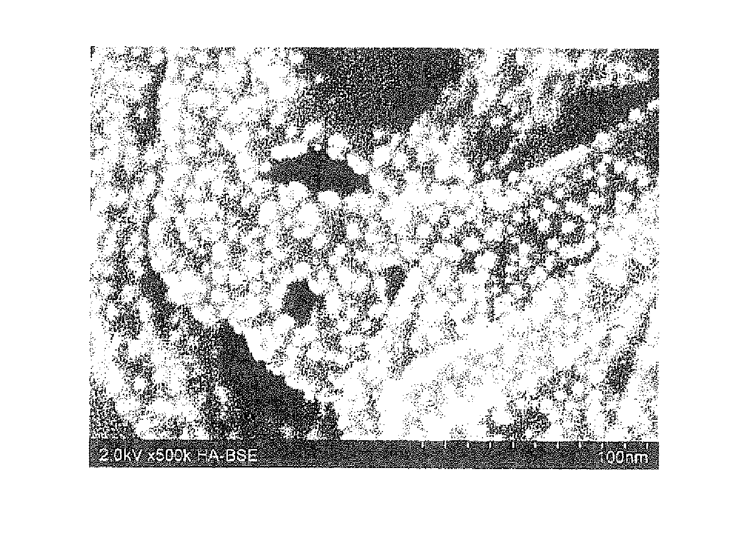
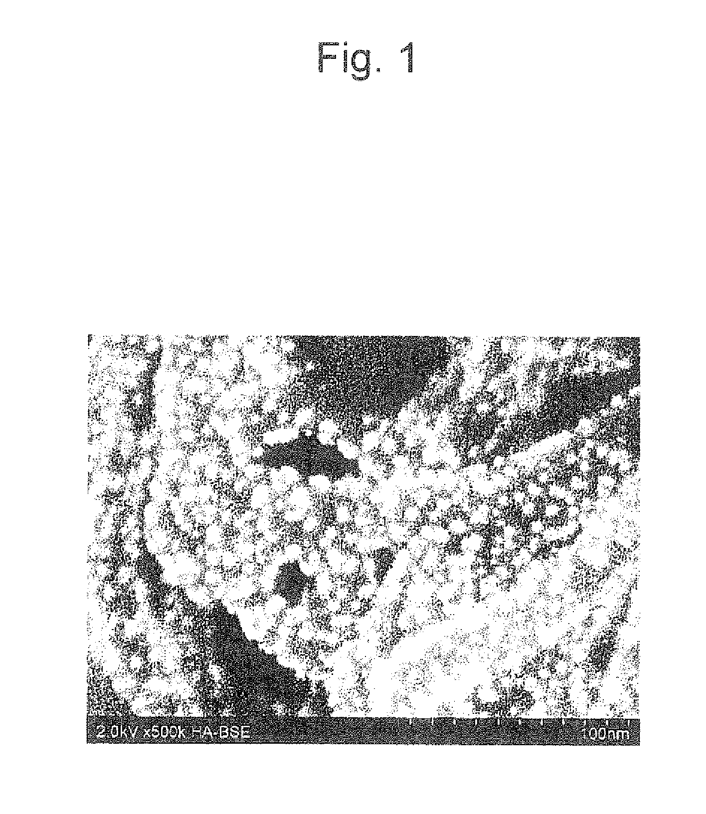
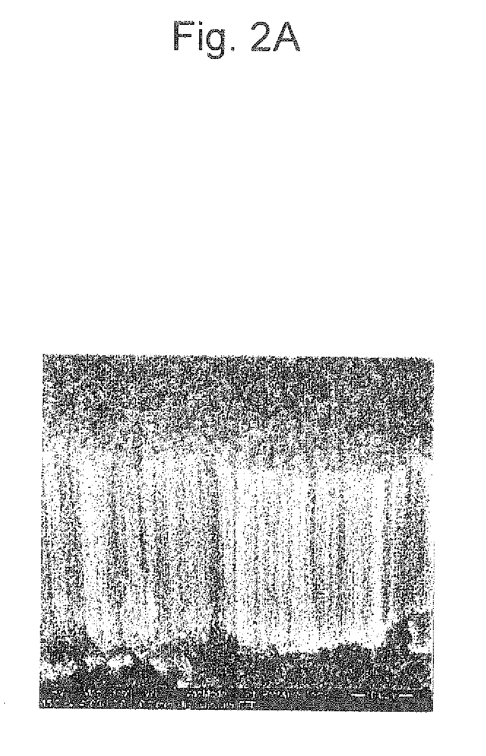
[0095]A porous film of carbon nanotubes vertically aligned on an Si substrate (manufactured by Hitachi Zosen Corporation; carbon density: 0.2 mg / cm2) was exposed to UV radiation in the air for 5 minutes. UV-42 (manufactured by Filgen, Inc.) was used for UV radiation.

[0096]A porous CNT film hydrophilized by UV treatment was immersed in a solution prepared by dissolving 11.8 mg of a dinitrodiammine Pt nitrate solution in 90 mL of water. Ethanol (76.5 mg) was added as a reducing agent to the solution, and then the solution was agitated for 1.5 hours. Subsequently, the temperature of the solution was increased to 90° C. to 95° C., followed by 8 hours of reflux. Then, 7.65 g of ethanol was additionally added and then the solution was further agitated for 2 hours.

[0097]After the solution was left to cool, the porous CNT film was removed from the solution and then washed with approximately 150 mL of water. Furthermore, the porous CNT film was dried naturally and the...


PUM

PropertyMeasurementUnit
mean particle diameteraaaaaaaaaa
thicknessaaaaaaaaaa
temperatureaaaaaaaaaa

Abstract

A method for producing an electrode catalyst substrate is provided herein, which comprises a carbon film forming step of forming a porous carbon film on a base, a hydrophilization step of hydrophilizing the porous carbon film, an immersion step of immersing the base in a solution prepared by dissolving catalytic metal ions in a polar solvent, and a reduction step of adding a reducing agent to the solution and thus reducing the catalytic metal ions. An electrode catalyst substrate obtained by the method and a polymer electrolyte fuel cell in which the electrode catalyst obtained by the method is used for anodes and/or cathodes are also provided herein. In the electrode catalyst of the present invention, fine catalyst particles are loaded in a uniform and highly dispersed manner.

Description

TECHNICAL FIELD[0001]The present invention relates to an electrode catalyst substrate and a method for producing the same, and a polymer electrolyte fuel cell. The present invention further specifically relates to an electrode catalyst substrate on which an electrode catalyst that is used for anodes and / or cathodes of various electrochemical devices (e.g., fuel cells, solar cells, lithium cells, water electrolytic devices, electrolytic devices for halogen acid, electrolytic devices for common salt, oxygen and / or hydrogen thickners, humidity sensors, gas sensors, and photocatalysts) is immobilized and a method for producing such substrate, and a polymer electrolyte fuel cell using such electrode catalyst.BACKGROUND ART[0002]In various electrochemical devices such as polymer electrolyte fuel cells or water electrolytic devices, a solid polymer electrolyte is shaped into a membrane, to both sides of which electrodes are each bonded, and is then used in the form of a membrane electrode ...

Claims


Application Information

Patent Timeline
Patent Type & Authority Applications(United States)
IPC IPC(8): H01M8/10H01M4/02B05D5/12B82Y99/00H01M4/86H01M4/88
CPCH01M4/8605H01M4/8807H01M4/8817H01M4/8842Y02E60/50H01M4/9083H01M4/926H01M2008/1095H01M4/885
Inventor SHINOZAKI, KAZUMAOKAMOTO, ATSUHITOHATANAKA, TATSUYATAKAHASHI, HIROAKITERADA, TOMOAKINAGATA, TAKAHIRO
Owner TOYOTA JIDOSHA KK
Why Eureka
Try Eureka