
Method of cladding monolithic silica body and separation medium

a monolithic silica and separation medium technology, applied in the field of cladding monolithic silica bodies and separation medium, can solve the problems of inability to make full use of the advantages of monolithic bodies, inability to directly use as separation medium, and easy damage of monolithic bodies alone, so as to achieve easy chemical treatment in the production process and ensure the effect of high production efficiency

Active Publication Date: 2011-01-06
GL SCI
View PDF9 Cites 16 Cited by
  • Summary
  • Abstract
  • Description
  • Claims
  • Application Information

AI Technical Summary

Benefits of technology

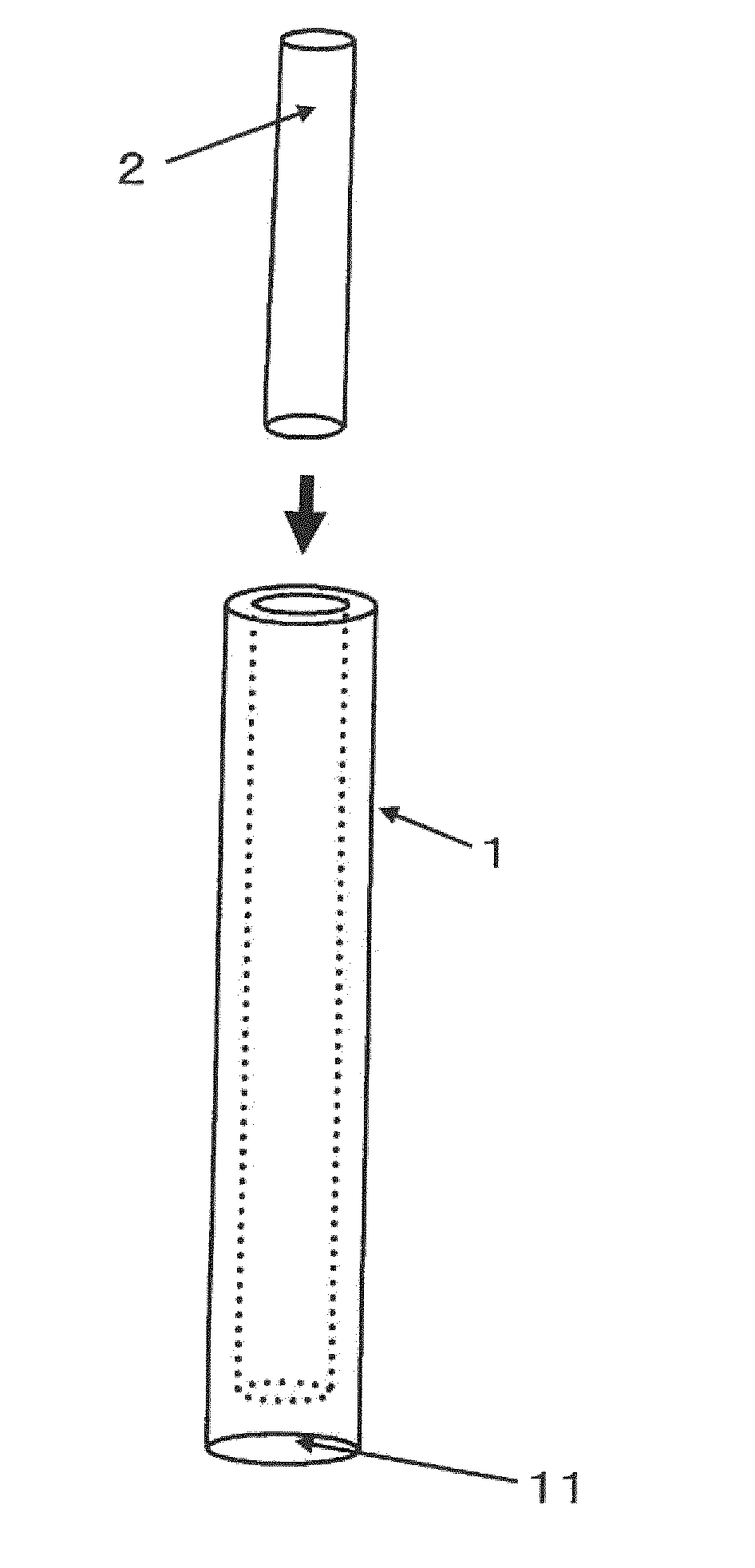
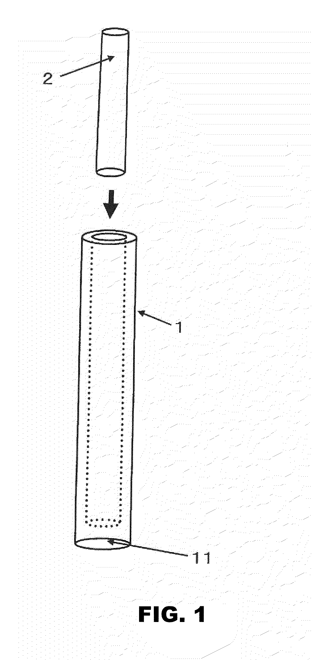
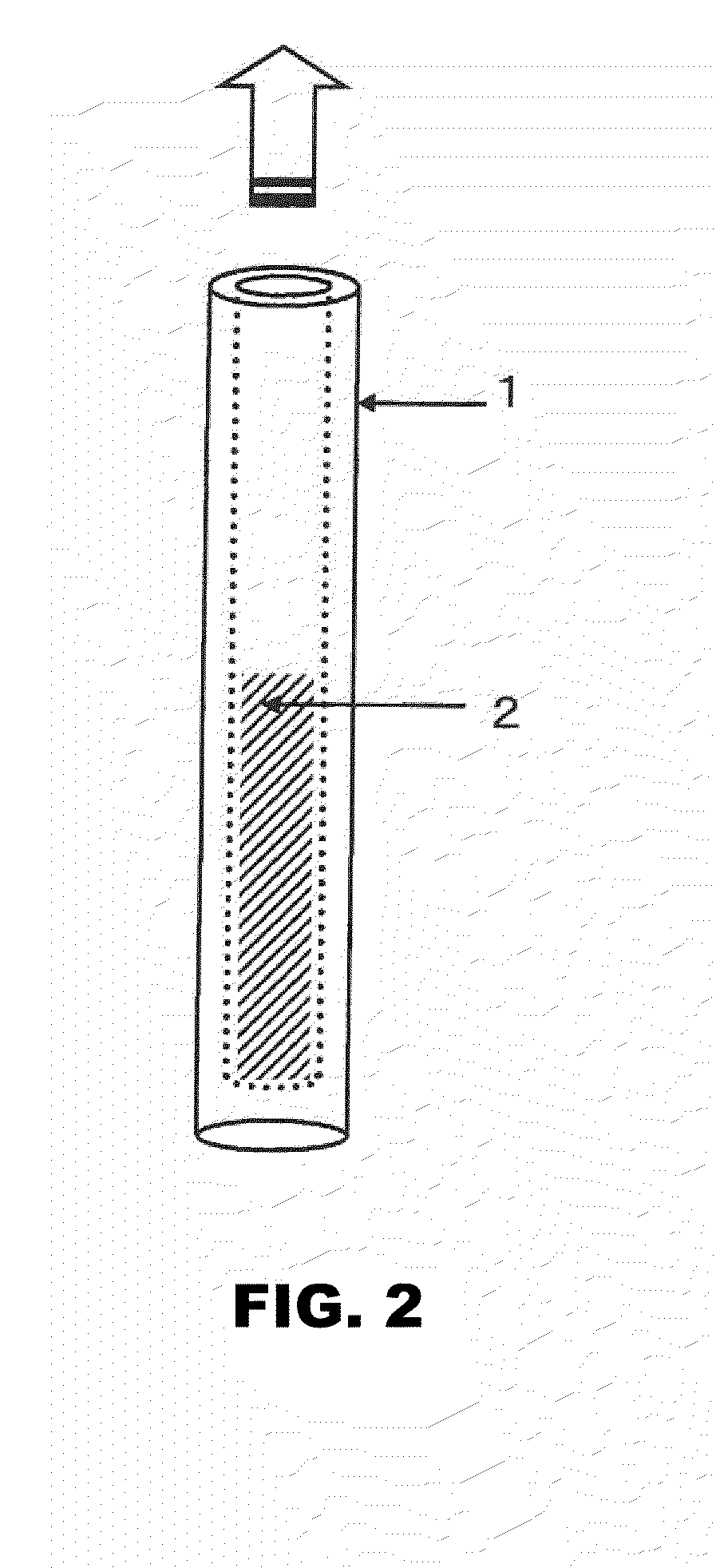
[0020]To solve the above problems of conventional arts, by preparing a monolithic body first and then coating it with glass having the same composition as the monolithic body, specific separation behaviors for other than SiO2 are eliminated, and the monolithic body and the glass are integrate to form a strong skeleton. Moreover, chemical treatment after coating with glass makes the monolithic body and the glass inner surface homogeneous, providing a separation medium capable of achieving extremely high analytical performance.
[0037]According to the present invention, only by coating a monolithic silica body with a glass body and employing appropriate temperature and pressure, the monolithic silica body and the glass body can be integrated very easily to achieve cladding without other physical or chemical coating methods.
[0039]As a result, the exterior of the separation medium is strongly protected, and chemical treatment in the production process is easy, providing a structure in which the homogeneity of the interior and the exterior is maintained.

Problems solved by technology

However, these monolithic bodies alone are easily damaged and cannot be directly used as a separation medium.
At present, however, these methods fail to make full use of the advantages of monolithic bodies.
Although it is necessary to form a most stable skeleton structure to prepare a cylindrical monolithic body having a high separation ability, making the side of the cylinder perfectly curved is difficult, and part of the ideal skeleton structure is broken by mechanical processing on the side.
Therefore, the method is incapable of making full use of the ability of monolithic bodies.
Further, to coat with resin, it is necessary to raise the temperature up to a point higher than the softening point of the resin, and cladding leads to degradation of a chemically treated portion, failing to demonstrate high performance.
Upon gelation, however, the volume is reduced and the portion near the inner surface of the capillary is pulled by the bonding force with the inner surface, making it difficult to form a homogeneous skeleton.
Due to the bonding to the inner surface, the original, stable monolithic skeleton cannot be maintained, and the resulting monolithic body has poorer properties than those synthesized using a monolithic body alone.
In this method, the inner surface of the gel mold is etched or the inner surface area is increased by forming a coat by pre-treating with solution or slurry to strengthen the contact with monomers to be packed, and so achieving close contact is impossible.
However, even this method requires a step of etching the inner surface of the glass mold.
Therefore, for strengthening the contact between the monomer and the mold as described above, it is not possible to achieve close contact between the two or to integrate them, and so the void formed between them still affects the separation ability.

Method used


Image

  • Method of cladding monolithic silica body and separation medium
  • Method of cladding monolithic silica body and separation medium
  • Method of cladding monolithic silica body and separation medium

Examples


example 1

[0113]The technique of the present invention is compared with a technique of preparing a monolith in a fused silica capillary.

[0114]In the present invention, 2.4 g of polyacrylic acid (HPAA available from Sigma-Aldrich Co., average molecular weight: 100,000 Dalton, average polymerization degree: 1390) was dissolved in 4.0 g of 1M nitric acid and 1.0 g of formamide, and 6.51 g of tetraethoxysilane was added to the solution and the mixture was mixed for 10 minutes to hydrolyze tetraethoxysilane.

[0115]The solution was poured into a cylindrical container having an inner diameter of 3 mmφ, and the whole container was sealed and kept at 40° C. for 2 days to cause phase separation and gelation. The solvent of the resulting gel was substituted with 1.5 M ammonia solution, and the solution was kept at 110° C. for 4 hours. Then the gel was dried in the air at 40° C. for 2 days and heat treated at 600° C. for 5 hours.

[0116]The resulting monolithic silica body was put in a low melting point gla...

example 2

[0146]The behavior of elution of pyridine, a basic compound, was examined using the column of Example 1 of the present invention and a commercially available HPLC monolithic column clad with PEEK resin.

[0147]Although pyridine sharply eluted before phenol in the column of the present invention, tailing of pyridine peak and phenol peak is observed in the conventional column. It is considered that since a chemically treated monolithic body is clad with resin, the resin is not treated and highly hydrophobic in the conventional column, and so the shape of peaks of water-soluble compounds such as pyridine and phenol became poor due to the hydrophobic difference between the inside and portions near the tube wall.

[0148]It is also considered that chemically treated portions have been degraded upon cladding with resin to allow silanol faces to be exposed, affecting the shape of peaks.

[0149]In the present invention, since the monolithic body is coated with glass having the same main component ...

example 3

[0152]The identification (normal phase) of the performance of clad glass depending on the difference in fusing temperatures when using Pyrex glass was performed as follows. Fusing at 650° C. has been proved to be unsatisfactory because no peak was found. Fusing at temperatures higher than that has been proved to be satisfactory because peaks of samples were found. The highest theoretical plate number was obtained at 725° C. It is thought that at temperatures of 760° C. or higher, the monolithic silica skeleton is influenced by contraction due to the high temperature, and therefore the theoretical plate number is decreased.

[0153]The above shows that the Pyrex glass body and the monolithic silica body are firmly fused at 700 to 800° C., providing a column which can be put into practical use.

[0154]As described above, the best result was obtained at 725° C. in this Example. It is considered that the result is close to the ideal, complete assimilation of the inner surface of glass and th...


PUM

PropertyMeasurementUnit
inner diameteraaaaaaaaaa
melting pointaaaaaaaaaa

Abstract

To use a monolithic silica body in chromatography with a HPLC column or a GC column and to simplify the use thereof as a separation medium, it is intended to provide a method of cladding a main body of a monolithic adsorbent or separating agent with glass so as to protect the outer surface, and to provide a separation medium prepared by the method. To this end, a monolithic silica body alone is formed by molding, and the molding is coated with a glass body; and then the glass body and the monolithic silica body are fused and integrated at the melting temperature of the glass body at an appropriate pressure. The surface of the resulting monolithic silica body clad with glass is strongly protected by the glass, and the homogeneity of the interior of the monolithic silica body is maintained, and thus uniform flow of a sample solution ensures analytical accuracy.

Description

TECHNICAL FIELD[0001]The present invention relates to a method of cladding a monolithic silica body which enables the monolithic silica body to be directly used as various separation columns, and a separation medium.[0002]A method and an instrument in which glass is used as a clad for a main body of a monolithic adsorbent or separating agent are proposed. The resulting separation medium is used in an HPLC column, a GC column, a column for column chromatography, a column for pretreatment, a guard column, a cartridge for solid phase, a passive sampler or the like.BACKGROUND ART[0003]Separation media prepared by packing particles in a cylindrical pipe or the like have been long widely used as an HPLC column, a cartridge for solid phase, a column for column chromatography, a column for pretreatment, a GC column and the like in chromatography.[0004]Monolithic bodies have been invented as an alternative to such particles and have attracted attention. Monolithic bodies have a three-dimensi...

Claims


Application Information

Patent Timeline
Patent Type & Authority Applications(United States)
IPC IPC(8): G01N30/02C03C27/00C03C23/00
CPCB01D15/20B01D15/22B01J20/103B01J20/28042B01J20/283B01J20/3257B01J2220/82B01J2220/825G01N30/50G01N30/6052G01N2030/528B01J2220/54
Inventor MIYAZAKI, SHOTATERASHIMA, HIROYUKINYUDO, MASAHIKOOHIRA, MASAYOSHIMORISATO, KEIFURUNO, MASAHIRO
Owner GL SCI
Learn More