

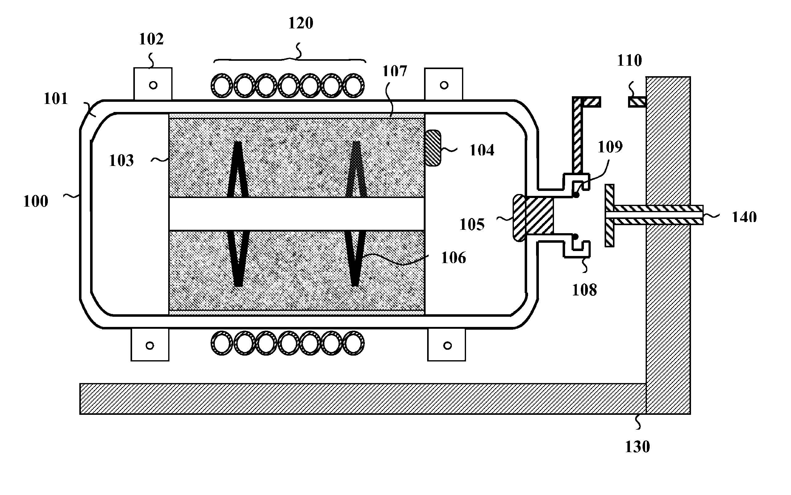
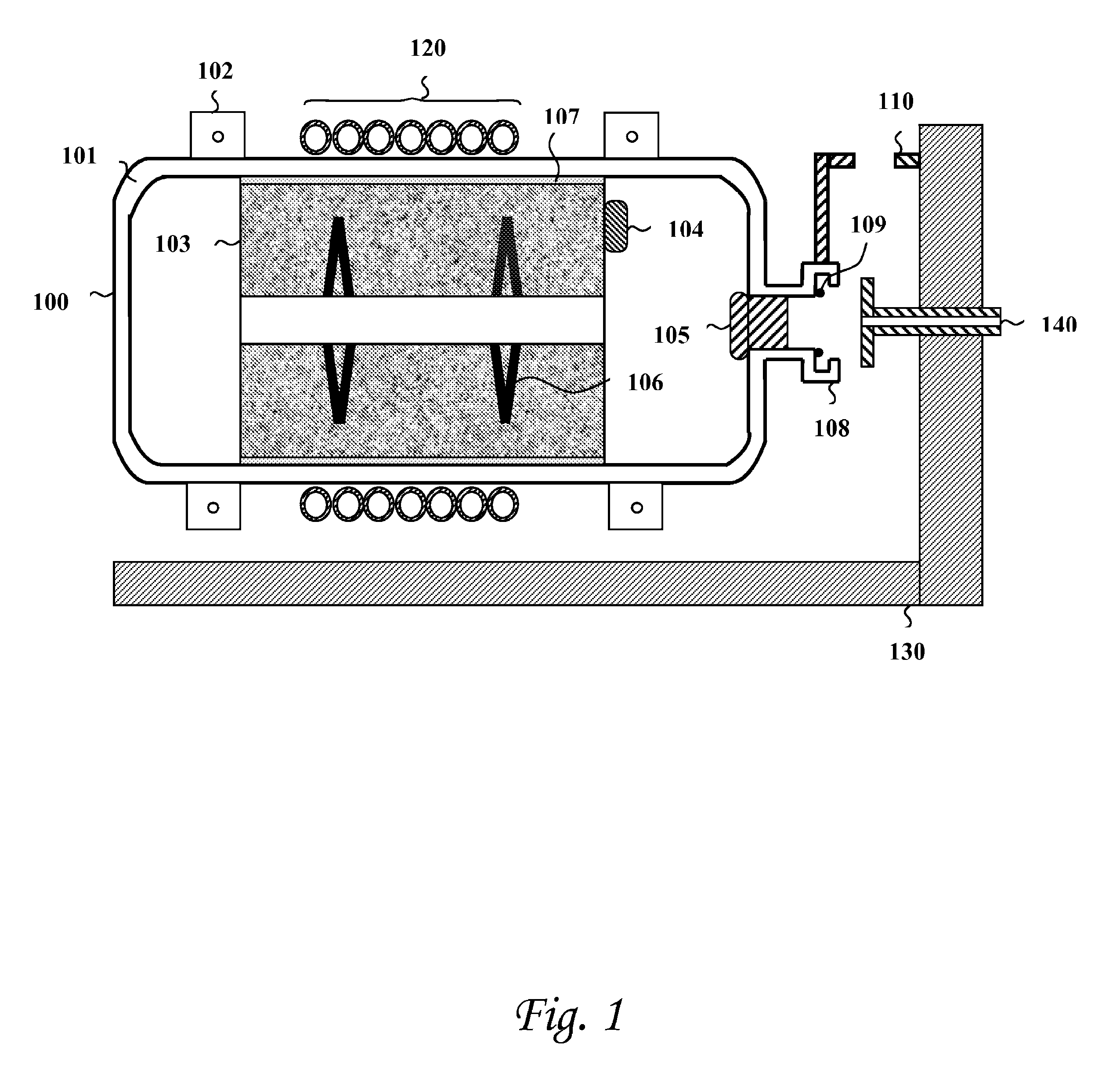
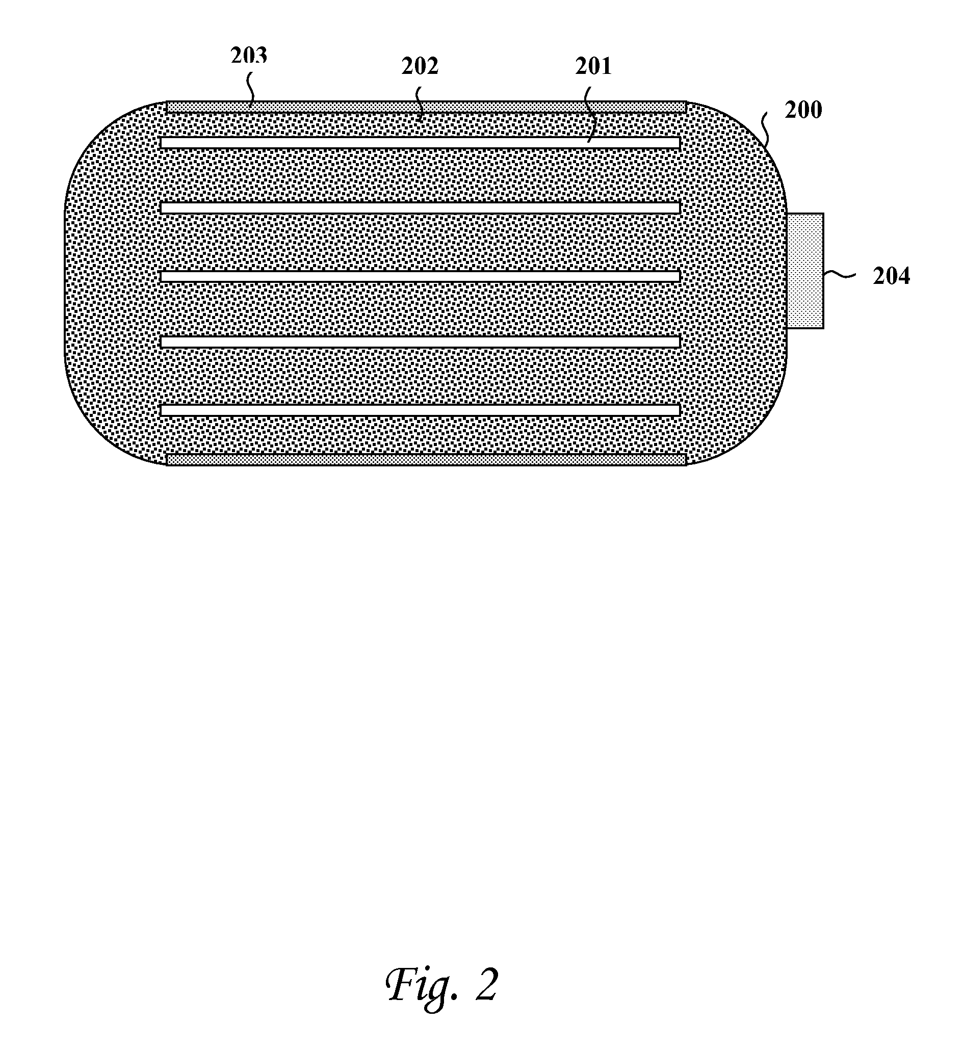
hydrogen storage tank
a hydrogen storage tank and hydrogen technology, applied in the field of hydrogen storage tanks, can solve the problems of high cost, high cost, and high risk of hydrogen release, and achieve the effects of low melting point metallic materials, easy transportation, and high conductivity interfa
- Summary
- Abstract
- Description
- Claims
- Application Information
AI Technical Summary
Benefits of technology
Problems solved by technology
Method used
Image

Examples
Embodiment Construction
[0034]The following description is provided, alongside all chapters of the present invention, so as to enable any person skilled in the art to make use of said invention. The description sets forth the best modes contemplated by the inventor of carrying out this invention. Various modifications, however, will remain apparent to those skilled in the art, since the generic principles of the present invention have been defined specifically to provide a hydrogen storage container.
[0035]In the following detailed description, numerous specific details are set forth in order to provide a thorough understanding of embodiments of the present invention. However, those skilled in the art will understand that such embodiments may be practiced without these specific details. Reference throughout this specification to “one embodiment” or “an embodiment” means that a particular feature, structure, or characteristic described in connection with the embodiment is included in at least one embodiment ...
PUM
| Property | Measurement | Unit |
|---|---|---|
| grain size | aaaaa | aaaaa |
| particle size | aaaaa | aaaaa |
| hydrogen chemical bonding | aaaaa | aaaaa |
Abstract
Description
Claims
Application Information