Piezoelectric thin-film tuning fork resonator

a thin-film resonator and piezoelectric technology, applied in piezoelectric/electrostrictive/magnetostrictive machines, piezoelectric/electrostriction/magnetostriction devices, electrical apparatus, etc., can solve the problem of large temperature coefficient (tce) of young modulus silicon, large length of additional step of silicon dioxide coating, etc. problem, to achieve the effect of increasing the merit of the oscillator

Inactive Publication Date: 2011-01-06
MICRO CRYSTAL
View PDF20 Cites 30 Cited by
  • Summary
  • Abstract
  • Description
  • Claims
  • Application Information

AI Technical Summary

Benefits of technology

[0015]According to still other embodiments of the present invention, the layout of the first and second electrodes is specifically designed to take advantage of the piezoelectric nature of quartz. According to these particular embodiment...

Problems solved by technology

One known problem with this type of resonator made from silicon is that the Young Modulus for silicon has a relatively large temperature coefficient (TCE).
One drawback of this known method ...

Method used


Image

  • Piezoelectric thin-film tuning fork resonator
  • Piezoelectric thin-film tuning fork resonator
  • Piezoelectric thin-film tuning fork resonator

Examples


first embodiment

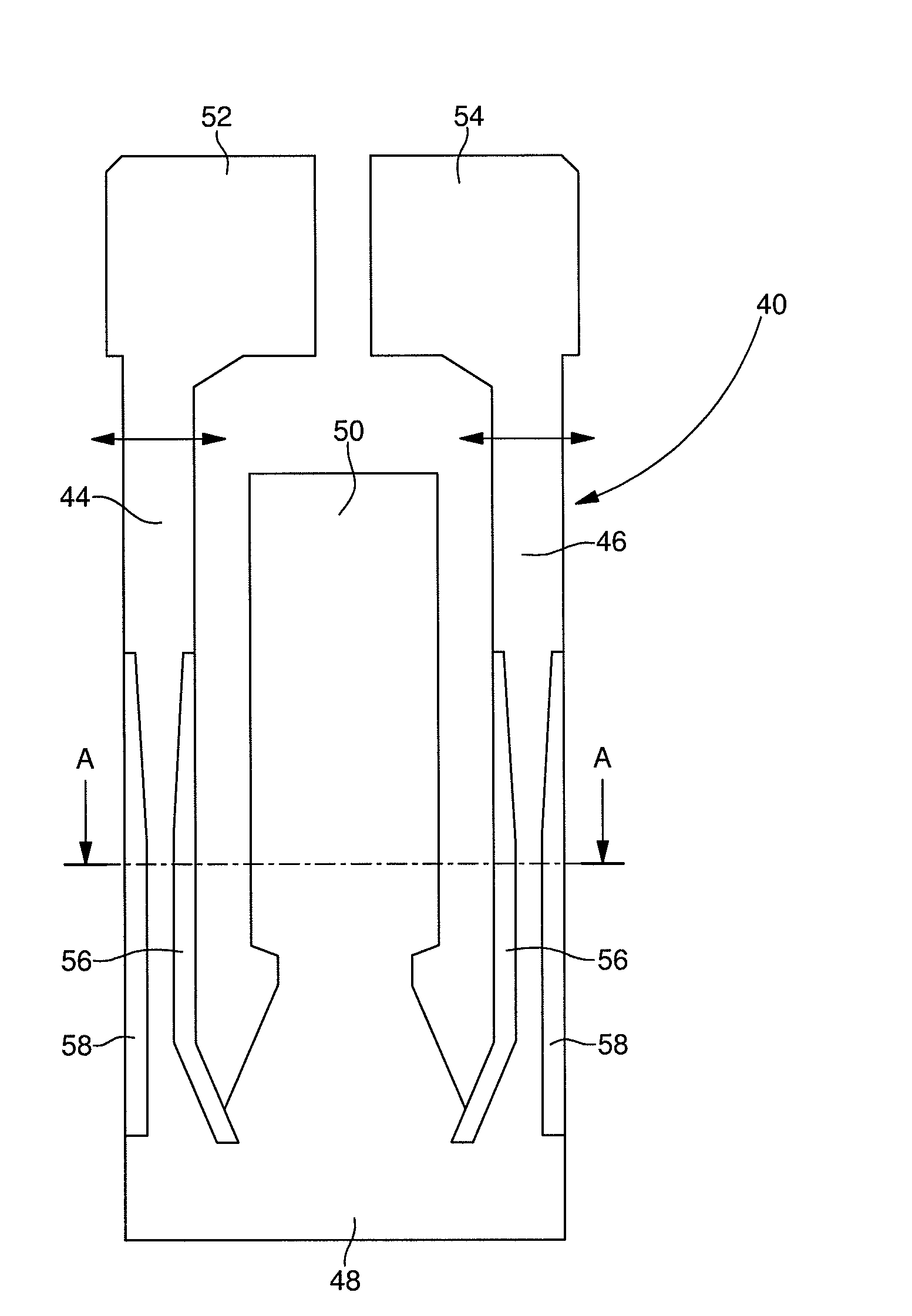
[0025]FIGS. 1A and 1B show a piezoelectric thin-film tuning fork resonator according to the invention. The resonator 40 includes a tuning fork shaped part with two vibrating arms 44 and 46 joined by a base 48. A fixed central arm 50 is further attached to the base in between the vibrating arms. The whole assembly is made out of a single piece of quartz.

[0026]In the illustrated example, the free end of each vibrating arm 44, 46 carries a flipper (referenced 52 and 54 respectively). By adding mass to the end of the vibrating arms, the flippers make it possible to reduce the length of the arms without altering the performances of the resonator. The presence of the flippers also ensures a better distribution of the mechanical stress along the arms.

[0027]As previously mentioned, the illustrated resonator comprises a central arm 50 that is located between arms 44 and 46 and is connected to the base 48. Central arm 50 is a fixing arm that is used for fixing resonator 40 to a support. As sh...

second embodiment

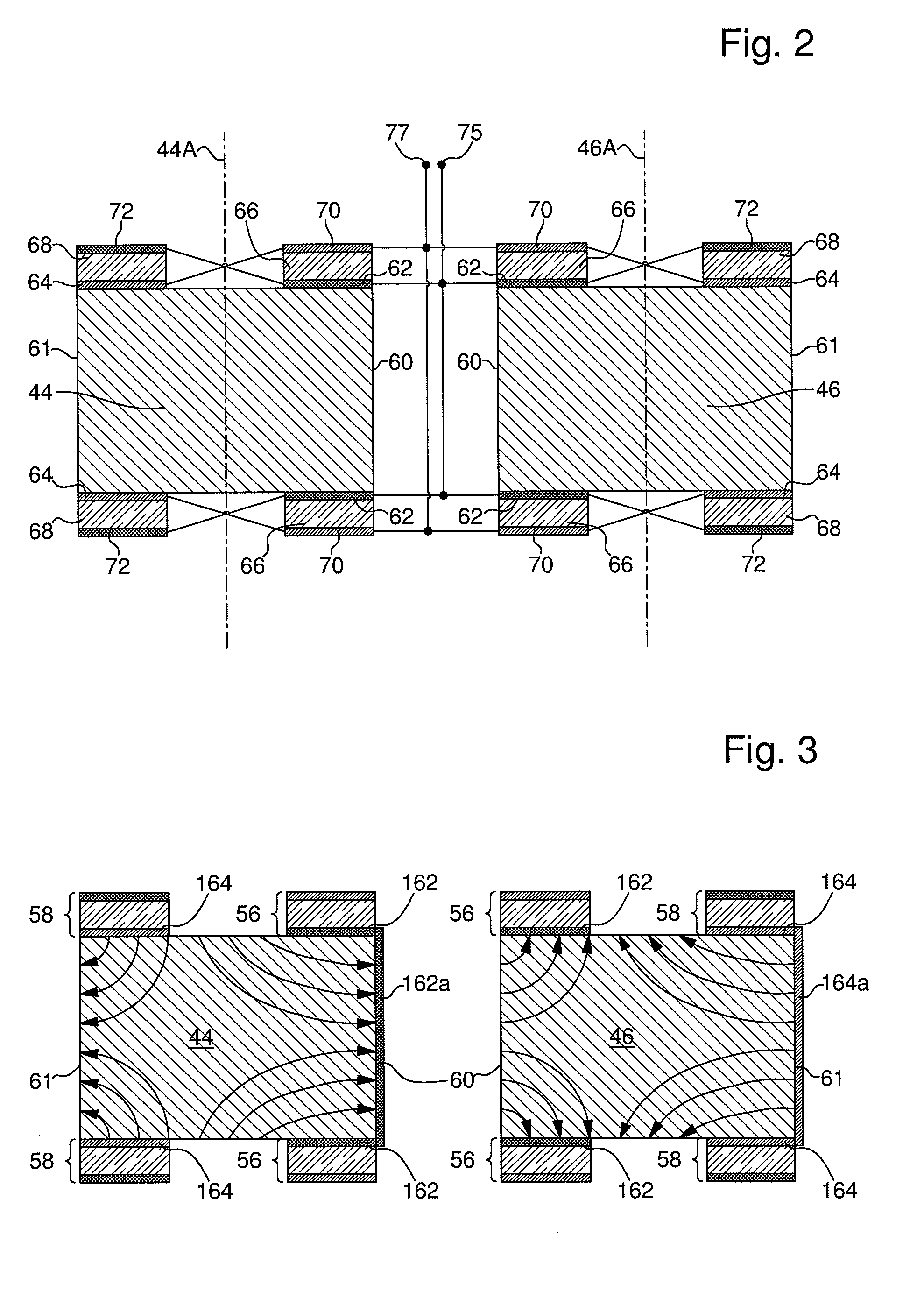
[0041]The thin-film tuning fork resonator schematically represented in FIG. 3 corresponds to the present invention. The resonator of FIG. 3 differs from that of FIG. 2 in that the first electrodes 162 on the main surfaces of vibrating arm 44 are joined together by an additional lateral portion 162a that covers the inner side (or edge) 60 of the vibrating arm 44. Furthermore, in a similar fashion, the second electrodes 164 on the main surfaces of vibrating arm 46 are joined together by an additional lateral portion 164a that covers the outer side (or edge) 61 of the vibrating arm 46. Considering the general layout of the electrostatic field lines represented in FIG. 3, it is straightforward to understand that the presence on one side of each arm of an additional lateral electrode portion increases the piezoelectric coupling between the quartz and the source of electrical excitation connected to the electrodes.

third embodiment

[0042]The thin-film tuning fork resonator schematically represented in FIG. 4 corresponds to the present invention. The resonator of FIG. 4 differs from that of FIG. 3 in that a first lateral electrode 262b is formed over the outer side (or edge) 61 of vibrating arm 44 opposite the additional lateral portion 262a, and in that in a similar fashion a second lateral electrode 264b is formed over the inner side (or edge) 60 of vibrating arm 46 opposite the additional lateral portion 264a. The first lateral electrode 262b is connected to the other first electrodes and the second lateral electrode 264b is connected to the other second electrodes. One possible way of implementing these connections is to deposit conductive tracks of metal film (not shown) using a vapor deposition mask. The conductive tracks are preferably formed between the electrodes and the base 48. Referring again to FIG. 3 and to the general layout of the electrostatic field lines, it is straightforward to understand th...


PUM


Abstract

The piezoelectric thin-film tuning fork resonator (40) comprises an integral tuning fork made out of a quartz crystal. The tuning fork comprises a base (48) and a pair of parallel vibrating arms (44, 46) extending from the base. Each of the vibrating arms carries:
    • first and second electrodes (62, 64) provided on at least one main surface of the arm, said first and second electrodes being formed respectively on an inner portion and on an outer portion of said one main surface, in such a way as to be spaced apart,
    • first and second piezoelectric thin films (66, 68) formed over the first and second electrodes respectively,
    • third and fourth electrodes (70, 72) formed over the first and second piezoelectric thin films respectively.

Description

FIELD OF THE INVENTION[0001]The present invention generally concerns piezoelectric thin-film resonators. The present invention more specifically concerns such resonators comprising an integral tuning fork, at least a first electrode arranged on each vibrating arm of the tuning fork, at least one thin film of piezoelectric material formed on each vibrating arm over the first electrode, and at least a second electrode formed on each vibrating arm over the piezoelectric thin film; the first and second electrodes being connected in such a way that applying of an alternating voltage causes the tuning fork to vibrate.BACKGROUND OF THE INVENTION[0002]Resonators corresponding to the above definition are known from the prior art. Patent document U.S. Pat. No. 7,002,284 discloses a piezoelectric thin-film resonator comprising a tuning fork having at least two tines (also called vibrating arms) and at least one stem (or base) coupling the tines. The tuning fork is made out of silicon. It is ob...

Claims


Application Information

Patent Timeline
IPC IPC(8): H01L41/047
CPCH03H9/215H03H9/131
Inventor DALLA PIAZZA, SILVIOSTAUB, FELIX
Owner MICRO CRYSTAL
Why Eureka
Try Eureka