Minimal surface area contact device for holding plaque to blood vessel wall

a contact device and small surface area technology, applied in the field of atherosclerosis occlusive disease treatment, can solve the problems of uncontrollable plaque disruption in the balloon angioplasty process, the lumen of the blood vessel at the site of treatment is usually somewhat larger, and the process of balloon angioplasty is not controlled. full dilatation to its intended size,

Active Publication Date: 2011-01-06
INTACT VASCULAR
View PDF132 Cites 95 Cited by
  • Summary
  • Abstract
  • Description
  • Claims
  • Application Information

AI Technical Summary

Benefits of technology

[0010]In accordance with the present invention, a tack device (and related method of deployment) for treating atherosclerotic occlusive disease comprises an annular band of durable, flexible material configured to be radially expandable outwardly under a spring or other expansion force and having a plurality of focal elevating elements on its outer annular periphery. The tack device is inserted in the blood vessel in a compressed state and installed in an expanded state by a catheter delivery mechanism after a balloon angioplasty procedure at one or more specific positions of loose plaque against the blood vessel wall. The focal elevating elements are designed to exert a holding force under expansion force pressure on the plaque while minimizing the amount of material surface area in contact with the plaque or blood vessel wall.
[0018]The present invention also encompasses the method of using the tack device to treat any plaque dissection in the blood vessel after balloon angioplasty by installing it with an expansion force against the plaque to hold it against the blood vessel walls. One preferred method encompasses one wherein drug eluting balloon angioplasty is first performed, and if there is any damage, disruption, dissection, or irregularity to the blood vessel caused by the balloon angioplasty mechanism, one or more tack devices may be used to tack down the damaged, disrupted, dissected, or irregular blood vessel surface, so as to avoid the need to install a stent and thereby maintain a ‘stent-free’ environment.

Problems solved by technology

When this occurs, greater pressure pumped into the balloon results in full dilatation of the balloon to its intended size.
The process of balloon angioplasty is one of uncontrolled plaque disruption.
The lumen of the blood vessel at the site of treatment is usually somewhat larger, but not always and not reliably.
If the plaque lifts completely in the direction of blood flow, it may impede flow or cause acute occlusion of the blood vessel.
However, stents have significant disadvantages and much research and development is being done to address these issues.
Depending on the location and the size of the artery, in-growth of intimal hyperplastic tissue from the vessel wall in between struts or through openings in the stent may occur and cause failure of the vascular reconstruction by narrowing or occlusion of the stent.
The recurrent stenosis is a problem because it causes failure of the stent and there is no effective treatment.
None of these methods have a high degree of long-term success.
Stents may also fracture due to material stress.
Structural integrity of stents remains a current issue for their use.
The scaffolding effect of the stent affects the overall mechanical behavior of the artery, making the artery less flexible.
Available stenting materials have limited bending cycles and are prone to failure at repeated high frequency bending sites.
Many artery segments are stented even when they do not require it, thereby exacerbating the disadvantages of stents.
When one attempts to place multiple stents and in the segments most in need of stenting, the cost is prohibitive since installation and material is required per stent.
The time it takes to do this also adds to the cost and risk of the procedure.

Method used


Image

  • Minimal surface area contact device for holding plaque to blood vessel wall
  • Minimal surface area contact device for holding plaque to blood vessel wall
  • Minimal surface area contact device for holding plaque to blood vessel wall

Examples


third embodiment

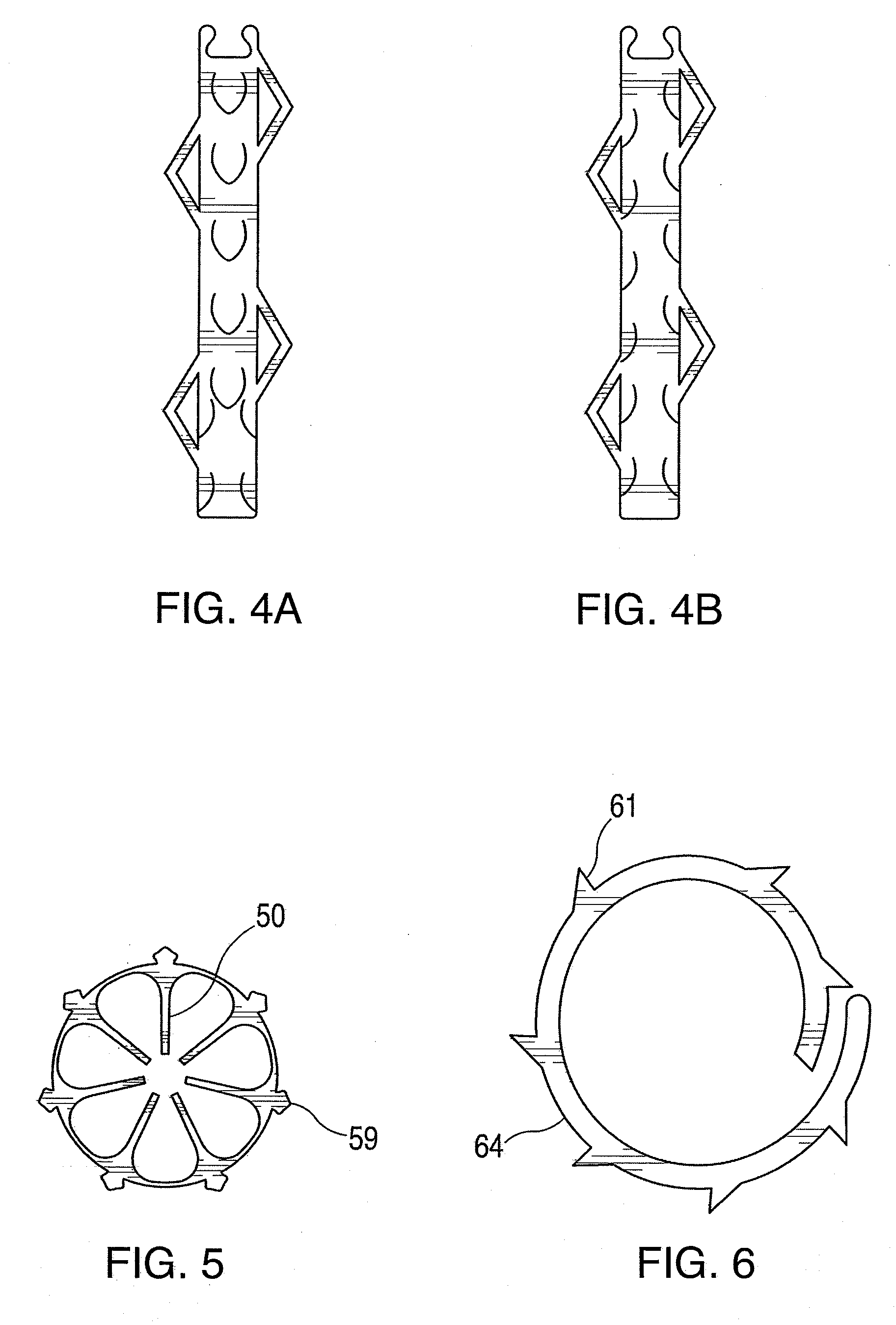
[0065]FIGS. 7A-7D show alternative shapes for FIG. 5 with a variety of different anchoring designs 72, 73, 78, 80. The fingers 76, 77 for bending the points flat for insertion are included with any of the designs. When the fingers are removed after pre-loading, and the flexible ring tack has been deployed, the inner area 74, 75 within the annular ring 79, 82 is left unobstructed.

[0066]Referring to FIG. 6, a fourth preferred embodiment of the previous plaque tack device is formed in a coil shape 64 with ends unjoined and with barbs or points 61 on its outer periphery. The ends are pulled longitudinally in opposite directions to flatten the annular band to a spiral shape extending linearly so that it can be carried around or inside the length of a tubular sheath into the blood vessel held in place by a retainer element. At the desired position in the blood vessel, the retainer element is released to allow the tack to expand back to its full-diameter annular shape against the plaque.

[0...

fifth embodiment

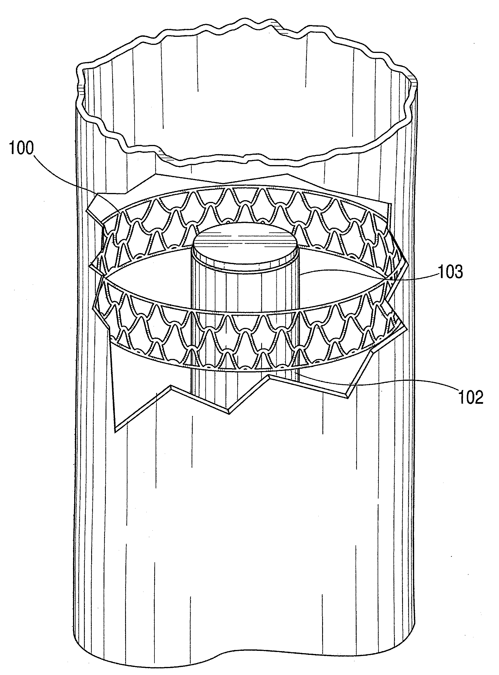
[0070]the previous plaque tack in the form of a metallic mesh tack is illustrated in FIGS. 19A-D, and its manner of deployment in FIGS. 20 and 21. In FIG. 19A, the metallic mesh tack is shown in end view having an annular band 100a formed of interleaved mesh, and outer points or barbs 100b. The metallic mesh tack may be laser cut or etched out of a metal tube form or made of thin metal wire which is looped and interleaved in a mesh that is welded, soldered, looped and / or linked together into the desired mesh shape. FIG. 19B shows the metallic mesh tack in side view with barbs projecting from the annular band 100a. The barbs on its outward surface will contact and embed into the wall of the blood vessel. FIG. 19C shows the metallic mesh tack at rest in its fully expanded state in perspective view, and FIG. 19D shows a section of the metallic mesh tack in a detailed view. The mesh pattern is specifically designed so that it can be compressed radially inward to a smaller-volume size fo...


PUM


Abstract

A tack device for holding plaque against blood vessel walls in treating atherosclerotic occlusive disease is formed as a thin, annular band of durable, flexible material having a plurality of focal elevating elements on its outer annular periphery for holding loose plaque under a spring or other expansion force against a blood vessel wall. The focal elevating elements are designed to exert a holding force on a plaque position while minimizing the amount of material surface area in contact with the plaque or blood vessel wall and reducing the potential of friction with the intraluminal surface. This approach offers clinicians the ability to perform a minimally invasive post-angioplasty treatment and produce a stent-like result without using a stent.

Description

[0001]This invention disclosure is a continuation-in-part of co-pending U.S. patent application Ser. No. 12 / 483,193, filed Jun. 11, 2009, which was a continuation-in-part of U.S. patent application Ser. No. 11 / 955,331, filed Dec. 12, 2007, of the same inventors.TECHNICAL FIELD[0002]This invention relates to treatment of atherosclerotic occlusive disease by intravascular procedures for pushing and holding plaque accumulated on the blood vessel walls out of the way for reopened blood flow.BACKGROUND OF INVENTION[0003]Atherosclerotic occlusive disease is the primary cause of stroke, heart attack, limb loss, and death in the US and the industrialized world. Atherosclerotic plaque forms a hard layer along the wall of an artery and is comprised of calcium, cholesterol, compacted thrombus and cellular debris. As the atherosclerotic disease progresses, the blood supply intended to pass through a specific blood vessel is diminished or even prevented by the occlusive process. One of the most ...

Claims


Application Information

Patent Timeline
Patent Type & Authority Applications(United States)
IPC IPC(8): A61M29/00A61F2/82A61F2/86A61F2/92
CPCA61F2/844A61F2/848A61F2/86A61F2/88A61F2/91A61F2/92A61F2230/005A61F2002/823A61F2002/825A61F2002/826A61F2002/8483A61F2220/0016A61F2/95A61F2230/0054A61F2250/0067A61F2/915A61F2/958A61F2002/91575A61F2220/0066A61L31/16A61F2/89A61F2002/8486A61F2002/91508A61F2002/91583A61F2002/9665
Inventor SCHNEIDER, PETERGIASOLLI, ROBERT
Owner INTACT VASCULAR
Why Eureka
Try Eureka