
Polyoxometalate flow-cell power system

a technology of polyoxometalate and flow cell, applied in the direction of indirect fuel cells, fuel cells, cell components, etc., can solve the problems of increasing the energy density of batteries by up to 25% through new electrode materials, and not delivering a substantial corresponding increase in runtime, so as to achieve the effect of not reducing the electrical conductivity

Inactive Publication Date: 2011-01-20
FC & ASSOC
View PDF3 Cites 22 Cited by
  • Summary
  • Abstract
  • Description
  • Claims
  • Application Information

AI Technical Summary

Benefits of technology

[0014]To obtain a high-power-density stack, a reduced form of liquid POM is fed to the stack of cells, in certain embodiments of the present invention, where the reduced form of liquid POM is efficiently oxidized into liquid products at the anodes. Air is fed and reduced at the cathodes, generating water as a byproduct. The POM-based flow cells that represent certain embodiments of the present invention can be recharged conventionally, like a battery, or reacted with a liquid fuel. The POM stack is not deleteriously impacted by the presence of common fuel impurities, such as the sulfur found in logistic fuels. Even were the sulfur in the fuel stream able to adsorb onto the electrode surface, the electrode's electronic conductivity does not decrease significantly. Thus, the electrochemical activity (the ability to capture electrons from the POM) of the flow cells that represent embodiments of the present invention are not significantly impacted by the presence of sulfur. Extra POM can be carried in a reservoir for the stack.

Problems solved by technology

For instance, one vendor has announced the release of a “24-hour battery” laptop, but the laptop can only run an older-generation operating system because newer operating systems are less power efficient.
Increasing battery energy density by up to 25% through new electrode materials will not deliver a substantial corresponding increase in runtime.
Internet media functions and handwriting / speech recognition will place even more strain on battery systems.
However, today's batteries, fuel cells, and other storage devices do not yet meet all the specifications.
However, because of key safety concerns and limited cycle life, Li-ion batteries are not suitable for large kW-sized EEMs.
In addition, most Li-ion batteries fall short of the minimum 1,000-hour target.
Lithium-ion batteries can rupture, ignite, or explode when exposed to high-temperature environments, such as an area that is prone to prolonged direct sunlight, or from short-circuiting.
In August 2007, Nokia recalled over 46 million lithium-ion batteries, warning that some of them might overheat and possibly explode.
The major disadvantage to these battery systems is the low energy density, similar to lead acid batteries (˜66-104 Whr / L).
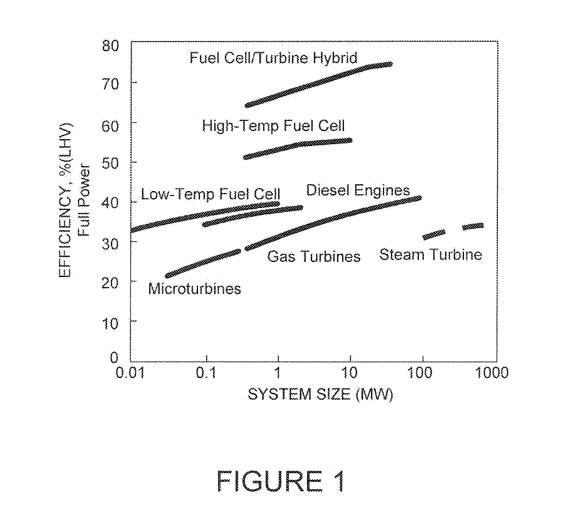
The promise of fuel cell technology, along with the promise of increased efficiency over diesel or gas turbine engines (see FIG. 1), has been on the horizon for decades, yet today's best fuel-cell systems are still not logistically practical for routine civilian or military applications.
Before a fuel cell can be integrated into a commercial design, a number of challenges are yet to be resolved.
The energy efficiency of a practical fuel cell is somewhat diminished by the energy needed to convert high-energy-density fuels, such as bio-diesel and diesel fuels, into hydrogen-rich gas needed by the fuel cell, and by the need to scrub sulfur and the reforming products from the fuel.
Even the more robust high-temperature fuel cells (e.g., solid oxide fuel cells) are poisoned with low levels of sulfur.
Desulphurization units add complexity to the overall fuel-cell system and extra weight, which leads to the reduction of overall system efficiency.
The need for reforming only adds to the startup and delayed responsiveness of the system.

Method used


Image

  • Polyoxometalate flow-cell power system
  • Polyoxometalate flow-cell power system
  • Polyoxometalate flow-cell power system

Examples


example 1

Catalyst Nanoparticle Preparation for the Pom Flow Cell and Pom Reactor

[0038]Since the electrochemical reaction occurs only at the catalyst surface, it is important to increase the available surface area per volume of catalyst used. Thus, to achieve high catalyst utilization, nanoparticles are synthesized on a carbon support. The carbon support prevents the nanoparticles from aggregating and provides a high electronic conductivity with good physical stability. The carbon-supported Pt and Pd nanoparticles and different compositions of noble-metal alloys (PtxPdy and PtxRuy) can be synthesized using a co-precipitation method. FIG. 10 shows a flow diagram of the catalyst-preparation steps, based on the co-precipitation method, according to one embodiment of the present invention.

example 2

Catalyst Ink Preparation for the Pom Flow Cell and Pom Reactor

[0039]First, an effective POM oxidizing electrode surface is prepared. To reduce the overpotential and to effectively oxidize POM, the anode electrode possesses both the electronic and ionic conducting networks. To fabricate a direct POM flow cell with such electrode properties, the anode catalyst ink is prepared by mixing the selected catalytic particles from Example 1 with Nafion® solution and water. This ink is applied onto the polymer membrane and dried to form the electrode surface. In this electrode surface, Nafion® provides an ion-conducting network, while the catalyst particles provide the electronic conducting network for a direct POM flow cell. However, if too much Nafion® solution is added to the catalyst particles during the ink-preparation step, the catalyst particles cannot maintain a good electronic conducting network, because each particle is separated by an excess amount of Nafion® polymer. On the other h...

example 3

Membrane Electrode Assembly Preparation for the Pom Flow Cell

[0041]Both the anode and cathode electrodes are fabricated by air brushing the inks from Example 2 onto a Nafion® polymer membrane. Nafion® membranes with thicknesses of 2, 5, and 7 milli-inches can be used to fabricate membrane electrode assemblies (MEAs). To secure the membrane while spraying the inks, the membrane is placed on a heated vacuum table 1102, as shown in FIG. 11. This elevated temperature will improve the drying rate of the excess water. After applying and drying the cathode ink first on one side of the membrane, the membrane is turned over for application and drying of the anode ink. Since POMs consist of large anion clusters with balanced cations, i.e., protons, there is a large electrical repulsion between this anion and the sulfonic acid groups within the Nation® membrane. Hence, a large diffusive flux of POM from the anode to the cathode of the flow cell through the Nafion® membrane is not seen. A very ...


PUM

PropertyMeasurementUnit
power densitiesaaaaaaaaaa
reduction potentialaaaaaaaaaa
volumeaaaaaaaaaa

Abstract

Embodiments of the present invention relate generally to redox flow batteries and, more specifically, to flow batteries that employ electron-ferrying redox compounds made from polyoxometalates (“POMs”). Embodiments of the present invention employ flow-battery technology that combines the fast electrochemical reaction of a battery with the fuel flexibility of a fuel cell to meet next-generation energy needs of a variety of power applications, including portable electronics used in military and commercial applications and large power modules that provide 550 W or more. To obtain a high-power-density stack, a reduced form of liquid POM is fed to the stack of cells, in certain embodiments of the present invention, where the reduced form of liquid POM is efficiently oxidized into liquid products at the anodes. Air is fed and reduced at the cathodes, generating water as a byproduct.

Description

CROSS-REFERENCE TO RELATED APPLICATION[0001]This application claims the benefit of Provisional Application No. 61 / 226,373, filed Jul. 17, 2009.TECHNICAL FIELD[0002]The present invention relates generally to redox flow batteries and fuel cells and, more specifically, to flow batteries that employ electron-ferrying redox compounds made from polyoxometalates.BACKGROUND[0003]The ever-growing expectations for more power and performance from mobile electronic products has created a large and growing need for energy-storage systems that are compact, lightweight, and powerful, with the demand for longer battery life increasing faster than the capacity of the technology to improve. Though lithium-ion (Li-ion) is the dominant technology for powering today's mobile devices, many experts believe the technology has become mature. Although electronic manufacturer's designers are constantly developing improved power-saving designs, and although second and third generations of new features do tend ...

Claims


Application Information

Patent Timeline
Patent Type & Authority Applications(United States)
IPC IPC(8): H01M8/06
CPCH01M4/8828H01M4/926H01M12/08H01M8/2455H01M8/04186H01M8/188H01M8/20Y02E60/50Y02E60/10
Inventor OHLSEN, LEROY JAMES
Owner FC & ASSOC
Learn More