Sealed type cell manufacturing method

a manufacturing method and seal technology, applied in the direction of sustainable manufacturing/processing, cell components, batteries, etc., can solve the problems of difficult automation, difficult to increase productivity, and difficult to fit and remove rubber stoppers, and achieve good weldability, good weldability, and good weldability.

Active Publication Date: 2011-02-03
TOYOTA JIDOSHA KK
View PDF8 Cites 23 Cited by
  • Summary
  • Abstract
  • Description
  • Claims
  • Application Information

AI Technical Summary

Benefits of technology

[0020]A multilayer film in which there are layered two or more resin layers having dissimilar compositions can be preferably used as the sealing film. Such a sealing film can combine several characteristics, and is hence preferable. Herein there can be preferably used, for instance, a multilayer film having a resin layer comprising a resin material (polyolefin resin material or the like), having good weldability, on at least one surface (i.e. the top face and / or bottom face), and a resin layer comprising a resin material relatively stiffer than the above material (for instance, a polyester resin material), on the other surface or in the interior of the multilayer film. A multilayer film having the above buildup affords better weldability and pressure-resistance sealability (property whereby the sealed state is preserved against rises in internal pressure). Preferably, the resin layer that forms the bottom face of the sealing film and the resin layer that forms the top face of the sealing film have a matrix (continuous phase) of the same type of resin composition. A sealing film having the above features exhibits good weldability (stack weldability) upon welding of the top face of one sealing film against the bottom face of another sealing film. This is advantageous, for instance, in embodiments where the second sealing film is stacked on and welded to the top face of the first sealing film.
[0021]A suitable specific example of the above multilayer film, for instance, may be multilayer film (typically a three-layer film) in which resin layers (polyolefin layers) comprising a polyolefin resin material (for instance polypropylene) are disposed at the top face and the bottom face, and a polyethylene naphthalate layer is disposed between the polyolefin layers. A multilayer film having the above configuration allows realizing, in particular, good weldability and pressure-resistance sealability. A multilayer film having the above configuration is also appropriately stiff, and hence makes for easier welding and hole-opening operations (i.e. affords good handleability), which is advantageous.
[0022]Other preferred examples of the above multilayer film include, for instance, a multilayer film in which a laser absorbing material (for instance, carbon black) is added to one or both (typically one) of the resin layers that make up the top face and the bottom face of the multilayer film. A multilayer film having the above configuration is suitable for welding by laser transmission welding. Therefore, the performance of the sealing film can be best brought out by using a multilayer film having the above configuration, in the case where welding of the sealing film is carried out by the laser transmission welding (in particular, in the case of stack welding). In a preferred multilayer film, for instance, a resin layer having added thereto a laser absorbing material is disposed at the bottom face, and a resin layer containing no laser absorbing material is disposed at the top face (i.e. the laser incidence side during laser transmission welding). Except for the presence or absence of added laser absorbing material, the composition of the resin layer in the bottom face and the resin layer in the top face may be substantially identical (preferably, the resin layers are polyolefin layers, for instance polypropylene layers). A multilayer film having the above configuration is suitable for stack welding by laser transmission welding. The resin layer having no laser absorbing material added thereto is preferably formed out of a resin material having good laser transmissivity. For instance, a multilayer film (typically, a three-layer film) may preferably be used such that a polyolefin layer having a laser absorbing material added thereto is disposed at the bottom face, a polyolefin layer having no laser absorbing material added thereto is disposed at the top face, and a polyethylene naphthalate layer is disposed between the polyolefin layers. Such a multilayer film has good laser weldability (in particular when stack welding is performed by laser transmission welding), and can afford excellent pressure-resistance sealability and handleability. The laser absorbing material that can be used is not particularly limited, and may be one, two or more types of laser absorbing material suitably selected from among, for instance, known pigment-based absorbing materials, dye-based absorbing materials and the like that are employed in the field of laser transmission welding. Carbon powders such as carbon black are an example of a preferably used laser absorbing material.

Problems solved by technology

The operations of fitting and removing the rubber stopper, however, are hard to automate, and thus productivity is difficult to increase.
Moreover, increases in inner pressure may cause the rubber stopper to float (to be pushed out).
The pressure-resistance sealability of the temporarily sealed state tends to be insufficient.
The sealing performance (in terms of preventing intrusion of moisture or the like) afforded by an elastic member such as rubber is insufficient upon temporary sealing, and thus intrusion of moisture into the temporarily sealed case remains a concern.

Method used


Image

  • Sealed type cell manufacturing method
  • Sealed type cell manufacturing method
  • Sealed type cell manufacturing method

Examples


example 1

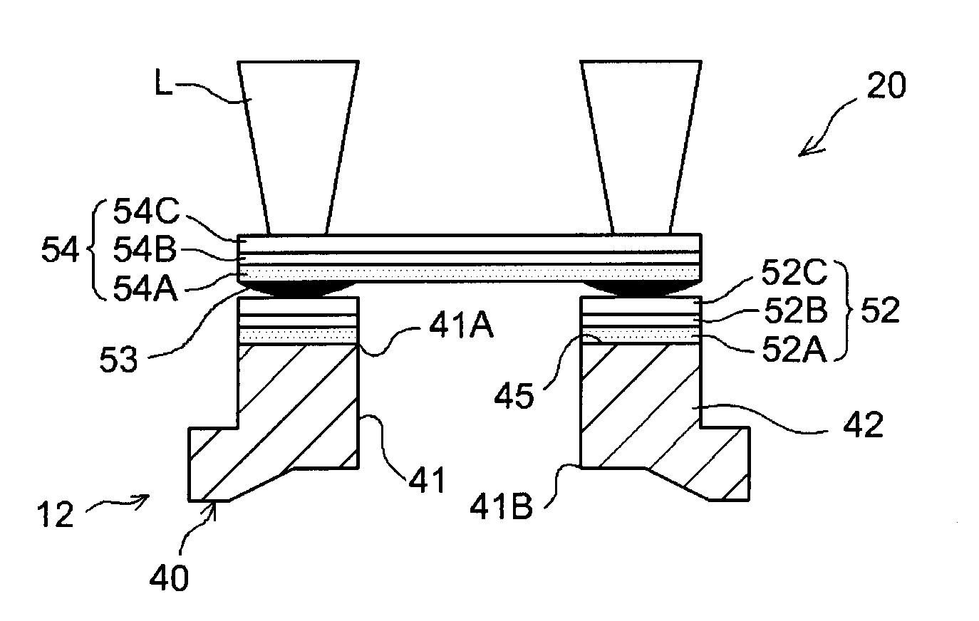
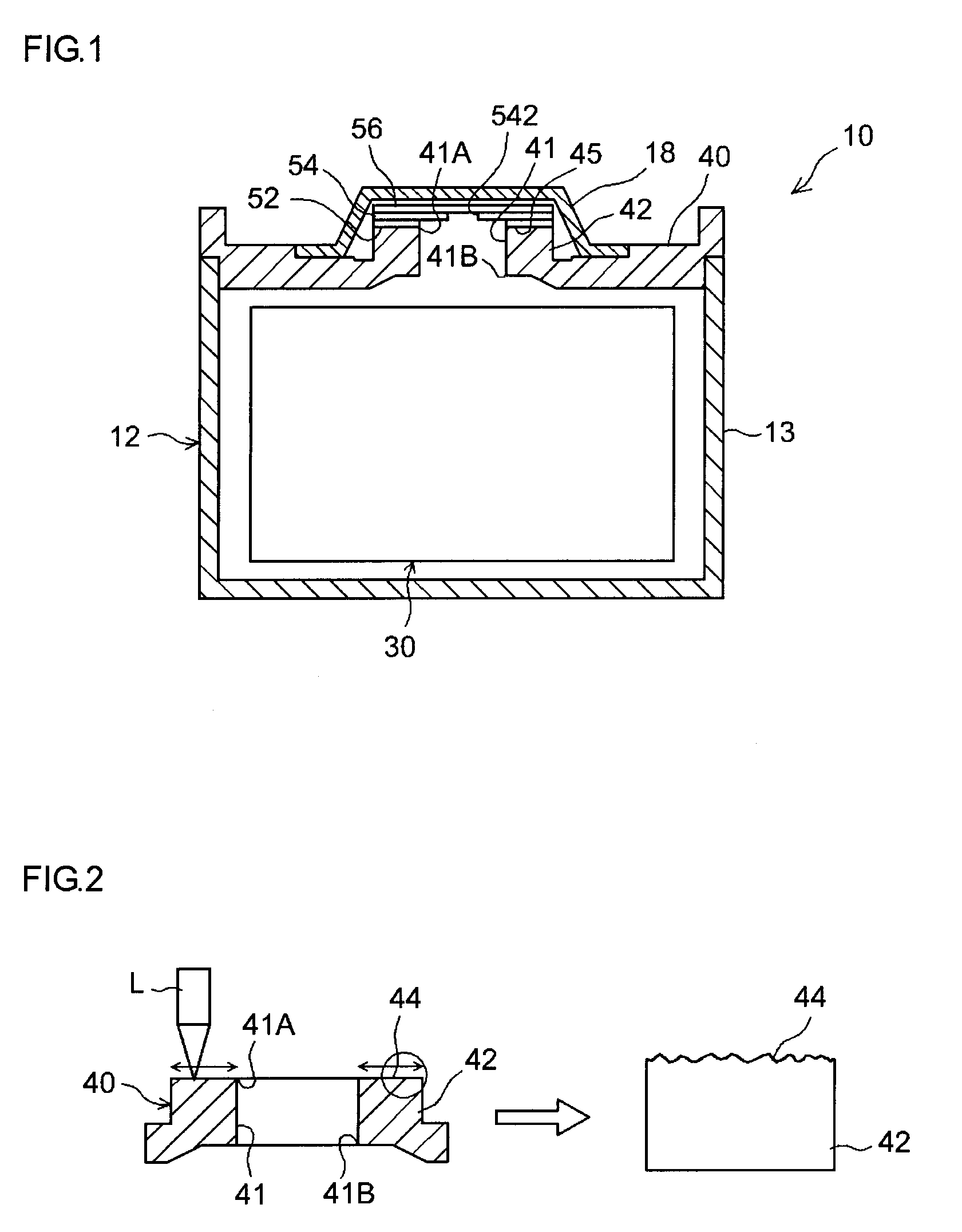
[0046]As illustrated for instance in FIG. 1, the lithium-ion cell according to the present example comprises an electrode body (wound electrode body) 30 in which an elongate sheet-like positive electrode and negative electrode are wound together in a flat manner, with an elongate-sheet separator interposed in between; and an external case 12 (in the present example, a flat box-like case) shaped so as to house the wound electrode body 30.

[0047]As illustrated in FIG. 7, the wound electrode body 30 can be manufactured in the same way as the wound electrode body in ordinary lithium-ion cells, by stacking an elongate sheet-like positive electrode (positive electrode sheet) 32 and a negative electrode (negative electrode sheet) 34, together with two elongate sheet-like separators (separator sheets, not shown), and winding the resulting stack in the longitudinal direction, after which the wound body is squashed flat from the side-face direction. In the present example, the positive electro...

example 2

[0071]The below-described evaluation test (electrolyte solution vapor exposure test) was carried out in order to assess the influence of the laser irradiation process on the welding strength of the resin films.

[0072]Specifically, Al plates (untreated Al plates) 0.8 mm thick, 13.5 mm wide and 110 mm long were prepared. A through-hole having a diameter of 1.6 mm was opened in the Al plates, such that the center of the through-hole stood substantially at the center of the plate, in the width direction, and at about 70 mm from one end of the plate, in the longitudinal direction. A laser irradiation process was carried out, under the conditions set out below, over an area having a diameter of 4.4 mm centered around the through-hole. As a result there were prepared Al plates for film welding according to samples 1 to 10. The surface area actually irradiated by the laser spot was of about ⅔ of the area scanned by the laser, at a scanning speed of 3000 mm / s.

[0073]Laser Irradiation Process C...

example 3

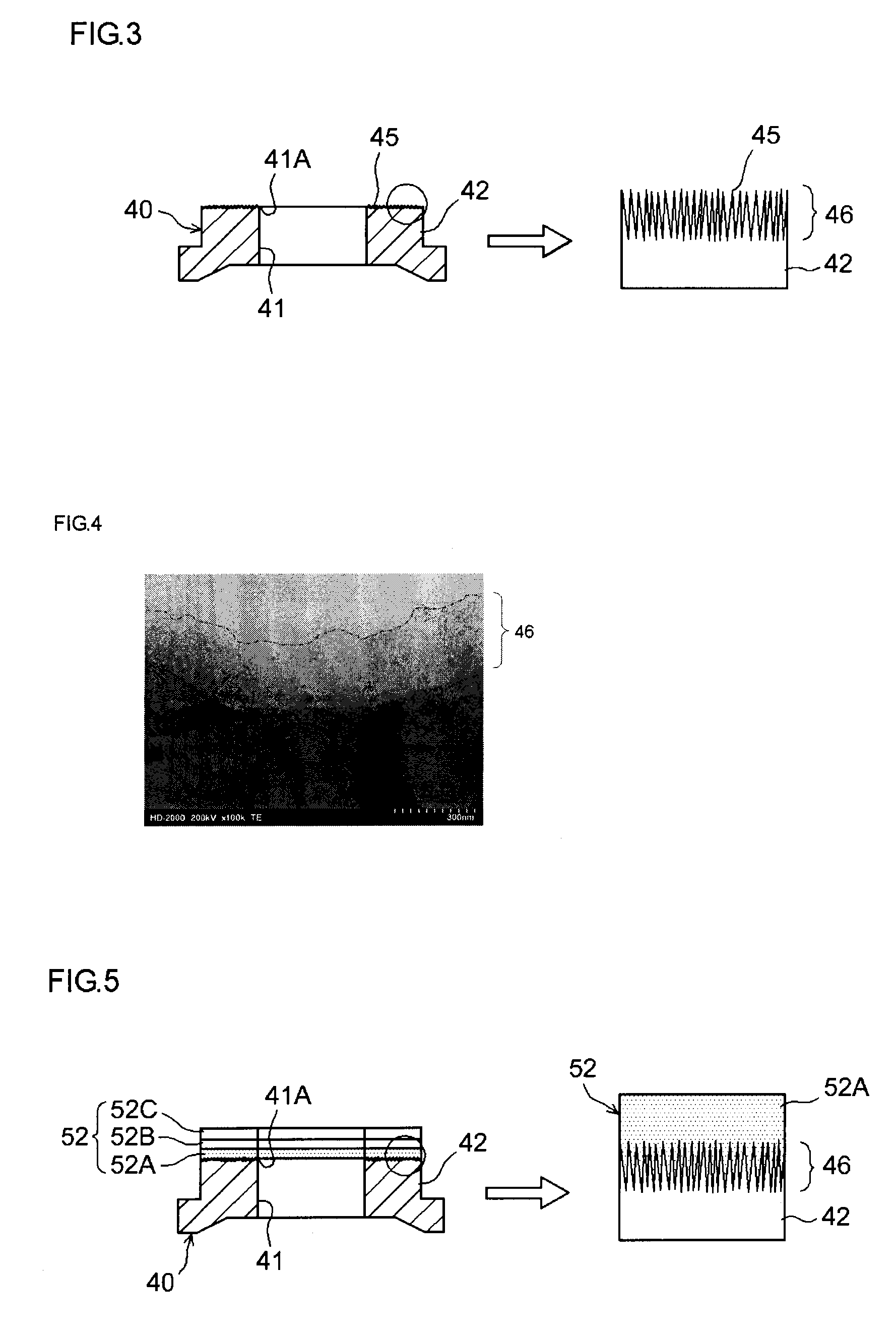
[0082]An Al plate (sample 17) was prepared through a laser irradiation process under the same conditions as in sample 3 of Example 2. Also, Al plates were prepared by subjecting an Al plate to a laser irradiation process under the above conditions, followed by argon sputtering onto the laser-treated surface, using an X-ray photoelectron spectroscopy (XPS) apparatus during 0.1 seconds (sample 18) or 1 minute (sample 19). The surface of the Al plate of sample 17 has formed thereon an aluminum oxide layer about 250 nm thick as a result of the above-described laser irradiation process. In the Al plates of samples 18, 19, the formed aluminum oxide layer is eroded by argon sputtering, from the top end of the oxide layer. The thickness of the aluminum oxide layer of the Al plate of sample 18 is of about 230 to 240 nm, while the thickness of the aluminum oxide layer of the Al plate of sample 19 is smaller than about 100 nm.

[0083]Film pieces identical to those of Example 2 were heat-welded t...


PUM

PropertyMeasurementUnit
thicknessaaaaaaaaaa
transmittanceaaaaaaaaaa
thicknessaaaaaaaaaa

Abstract

A cell assembly (20) is formed by arranging an electrode body and electrolyte in an external case (12) having a through hole (41). A laser is applied to an annular portion (formed by Al or Al-based alloy) surrounding an opening end (41A) of the through hole (41) toward outside the case so as to form a welded base (45). A sealing film (54) is welded to the surface of the welded base directly or via a base film (52) welded in advance, so as to temporarily seal the through hole (41). The cell assembly (20) in the temporarily sealed state is subjected to initial charge and then a hole is opened through the film (54) so as to form a gas discharge passage for communication between inside and outside of the case (12), thereby discharging an excessive gas from the case (12) outside.

Description

TECHNICAL FIELD[0001]The present invention relates to a sealed type cell such as a lithium-ion cell.[0002]The present application claims priority to Japanese Patent Application No. 2008-021791, filed Jan. 31, 2008, the entire contents of which are hereby incorporated by reference.BACKGROUND ART[0003]Recent years have witnessed a growing importance of sealed type secondary cells such as lithium-ion cells, for instance as vehicle on-board power sources, and as power sources in personal computers, cell phones and the like. Lithium-ion cells, in particular, are lightweight and afford high energy densities, and are thus expected to become preferred high-output on-board power sources.[0004]A typical method for manufacturing a sealed type cell of the above kind involves housing, in a metallic external case, a power-generating element (electrode body) that is provided with a positive electrode, having a positive electrode active material, and a negative electrode, having a negative electrod...

Claims


Application Information

Patent Timeline
Patent Type & Authority Applications(United States)
IPC IPC(8): H01M10/04B23K26/22H01M2/08H01M50/184H01M50/186H01M50/193H01M50/197H01M50/198H01M50/636
CPCH01M2/08H01M2/1241H01M2/361H01M2/365Y10T29/4911H01M10/0525H01M10/446Y02T10/7011H01M10/0413Y02E60/10H01M50/3425H01M50/636Y02P70/50H01M50/184H01M50/186H01M50/193H01M50/198H01M50/197H01M10/058H01M2220/20H01M50/191H01M10/34Y02T10/70
Inventor KOMATSUKI, MASATONAKAZAWA, TAKASHIYUGAHARA, KAORUKONDOU, HIROYAFUJIKA, TAKATO
Owner TOYOTA JIDOSHA KK
Why Eureka
Try Eureka