Carbon fiber carbon composite molded body, carbon fiber-reinforced carbon composite material and manufacturing method thereof

a carbon fiber and composite material technology, applied in the direction of solid-state devices, metallic material coating processes, electrical devices, etc., can solve the problems of insufficient thermal conductivity, diamond components have the problem of high cost, and materials are subject to some restrictions, etc., to achieve excellent thermal conductivity excellent thermal conductivity

Inactive Publication Date: 2011-02-10
TOYO TANSO KK
View PDF7 Cites 27 Cited by
  • Summary
  • Abstract
  • Description
  • Claims
  • Application Information

AI Technical Summary

Benefits of technology

[0052]By forming the carbon fiber-reinforced carbon composite material of the present invention using the carbon fiber-carbon composite formed body of the present invention, there can be provided a carbon fiber-reinforced carbon composite material exhibiting excellent thermal conductivity in every direction in the plane containing the X-axis and the Y-axis.
[0053]According to the manufacturing method of the present invention, a carbo

Problems solved by technology

However, the thickness of these materials that can be attained by manufacturing is only about a few millimeters, and these materials are therefore subject to some restriction in the heat sink design phase.
In addition, diamond components have the problem of high cost.
Even if the gas reaches the inside of the preform, a sufficiently high thermal conductivity may not be achieved because the crystalline morphology of pyrolytic carbon formed differs depending on the type of carbon fibers.
However, heat spread to the base cannot be expected, which makes it difficult to rapidly transfer heat produced in the semiconductor to the base.
On the other hand, if the heat sink material is placed so that the direction of the carbon fibers is parallel to the semiconductor, this makes it difficult to conduct heat from the semiconductor because the thermal conductivity of the carbon

Method used


Image

  • Carbon fiber carbon composite molded body, carbon fiber-reinforced carbon composite material and manufacturing method thereof
  • Carbon fiber carbon composite molded body, carbon fiber-reinforced carbon composite material and manufacturing method thereof
  • Carbon fiber carbon composite molded body, carbon fiber-reinforced carbon composite material and manufacturing method thereof

Examples


example 1

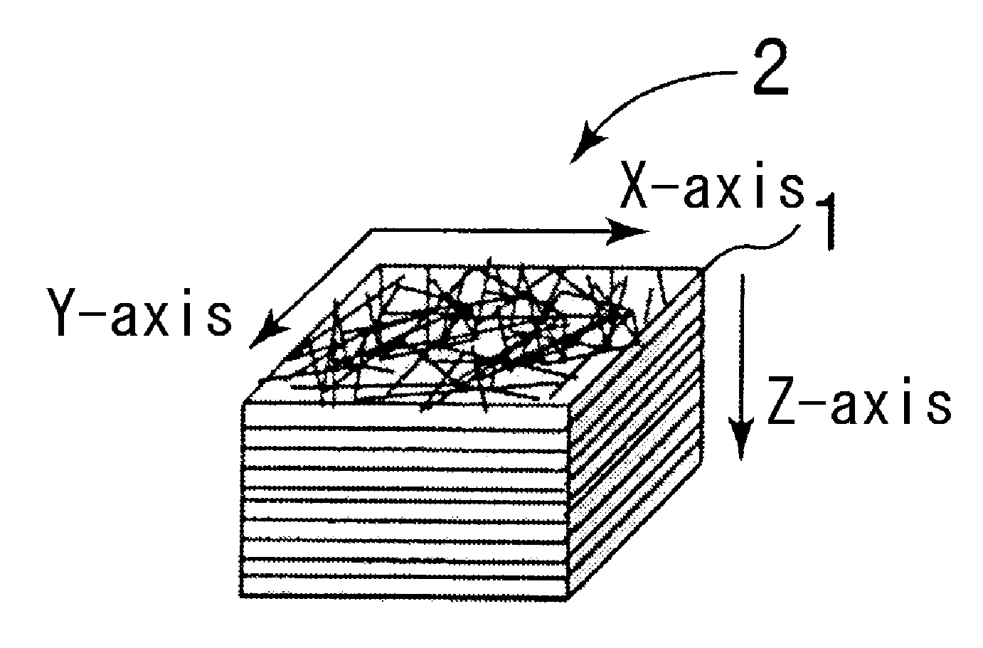
[0059]Pitch-based carbon fibers (a yarn of 12000 (12K) filaments, average diameter: 9 μm, density: 1.93 Mg / m3) were cut into lengths of about 30 to 100 mm, and a sizing agent was removed therefrom using acetone or the like. The carbon fibers were dispersed in random directions, and then bonded together with 30 parts by mass of phenol resin relative to 100 parts by mass of carbon fibers, thereby preparing sheet-like prepregs (thickness: approximately 0.5 mm) in which the carbon fibers were dispersed randomly in the plane containing the X and Y axes. The prepregs were preliminarily dried in an oven at approximately 100° C. Approximately 100 prepregs after being dried were laminated and pressed into a certain form using a hot press under the conditions of a pressure of 0.3 MPa and a temperature of 150° C. Next, the form was subjected to heat treatment at approximately 2000° C., thereby obtaining a carbon fiber laminate having a size of 50 mm×50 mm×50 mm. The density of the carbon fiber...

example 2

[0072]A carbon fiber laminate was filled with pyrolytic carbon in the same manner as in Example 1, then repeatedly subjected to immersion into an easily graphitizable pitch of low quinoline insoluble content and heat treatment, and thereafter subjected to heat treatment for graphitization.

[0073]The density of the carbon fiber laminate was 0.25 Mg / m3, the density thereof after being filled with pyrolytic carbon was 1.75 Mg / m3, and the density thereof after being subjected to immersion into pitch and heat treatment was 1.82 Mg / m3. The crystal thickness d between adjacent (112) planes of graphite crystal after being subjected to graphitization treatment was 8 nm.

[0074]Determinations were made in the same manners as in Example 1, and the determination results are shown in TABLE 1.

example 3

[0075]Pyrolytic carbon was contained in a carbon fiber laminate in the same manner as in Example 1, and the carbon fiber laminate was then repeatedly subjected to immersion into a pitch and heat treatment, and then subjected to heat treatment for graphitization, thereby obtaining a carbon fiber-reinforced carbon composite material.

[0076]The density of the carbon fiber laminate was 0.20 Mg / m3, the density thereof after containing pyrolytic carbon was 1.75 Mg / m3, the density thereof after being impregnated with pitch was 1.95 Mg / m3, and the crystal thickness d between adjacent (112) planes of graphite crystal was 8 nm.

[0077]Determinations were made in the same manners as in Example 1, and the determination results are shown in TABLE 1.


PUM

PropertyMeasurementUnit
Thicknessaaaaaaaaaa
Nanoscale particle sizeaaaaaaaaaa
Volumeaaaaaaaaaa

Abstract

To obtain a carbon fiber-reinforced carbon composite material exhibiting excellent thermal conductivity in every direction in the plane containing the X and Y axes. A carbon fiber-carbon composite formed body in which a number of sheet-like dispersions containing pitch-based carbon fibers dispersed therein randomly in the plane containing the X and Y axes are laminated into a carbon fiber laminate, and pyrolytic carbon is deposited on the surfaces of the carbon fibers of the carbon fiber laminate to coat around the carbon fibers, whereby the carbon fiber laminate is filled with the pyrolytic carbon, and a carbon fiber-reinforced carbon composite material obtained using the carbon fiber-carbon composite formed body.

Description

TECHNICAL FIELD[0001]This invention relates to a carbon fiber-carbon composite formed body, a carbon fiber-reinforced carbon composite material and a manufacturing method thereof.BACKGROUND ART[0002]In the field of electronic devices using silicon or compound semiconductors, significant technology advances are being achieved, and the frequency and power conversion capacity used are expected to further increase. Along with this, the quantity of heat produced from electronic devices continues to increase. Therefore, so-called heat sink materials capable of helping electronic devices dissipate a greater quantity of heat at a higher rate according to the design are becoming more and more essential.[0003]Among the materials currently used as heat sink materials are copper molybdenum, copper tungsten and aluminum nitride. The thermal conductivities of these heat sink materials are lower than 250 W / mK. Because of the above-mentioned advances in semiconductor technology, there is demand for...

Claims


Application Information

Patent Timeline
IPC IPC(8): F28F7/00B32B5/02
CPCH01L23/373C25D7/12C04B35/522C04B35/62873C04B35/83C04B2235/5248C04B2235/526C04B2235/5264C04B2235/5268C04B2235/614C04B2235/77C04B2235/9607C04B2237/385C25D7/00C23C18/54C22C47/08C22C49/14C04B35/632C04B35/63496C04B35/645C04B35/653C04B2235/656C04B2235/661C04B2237/525C04B2237/582C04B2237/61C04B2237/704H01L2924/0002B32B18/00H01L2924/00C04B2235/616Y10T428/249928
Inventor TAKEDA, AKIYOSHI
Owner TOYO TANSO KK
Why Eureka
Try Eureka