
Coated sleeved oil and gas well production devices

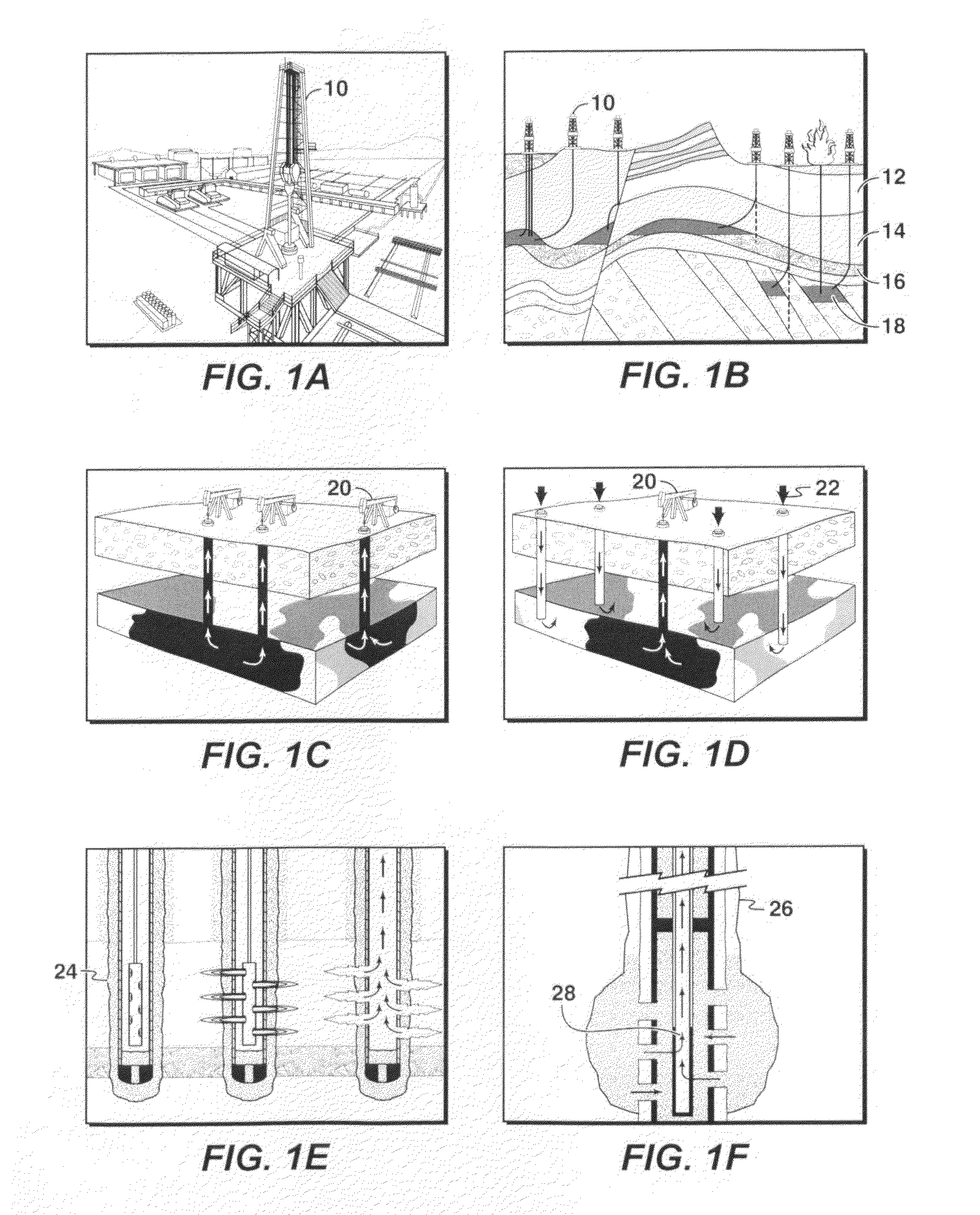
a well and production device technology, applied in the direction of drilling casings, drilling pipes, borehole/well accessories, etc., can solve the problems of not being very efficient, cumbersome geometry of long pipe sections, and restricting the requirement of many oilfield components, so as to reduce friction, wear, corrosion, erosion and deposits

Active Publication Date: 2011-02-24
EXXONMOBIL UPSTREAM RES CO
View PDF58 Cites 78 Cited by
  • Summary
  • Abstract
  • Description
  • Claims
  • Application Information

AI Technical Summary

Benefits of technology

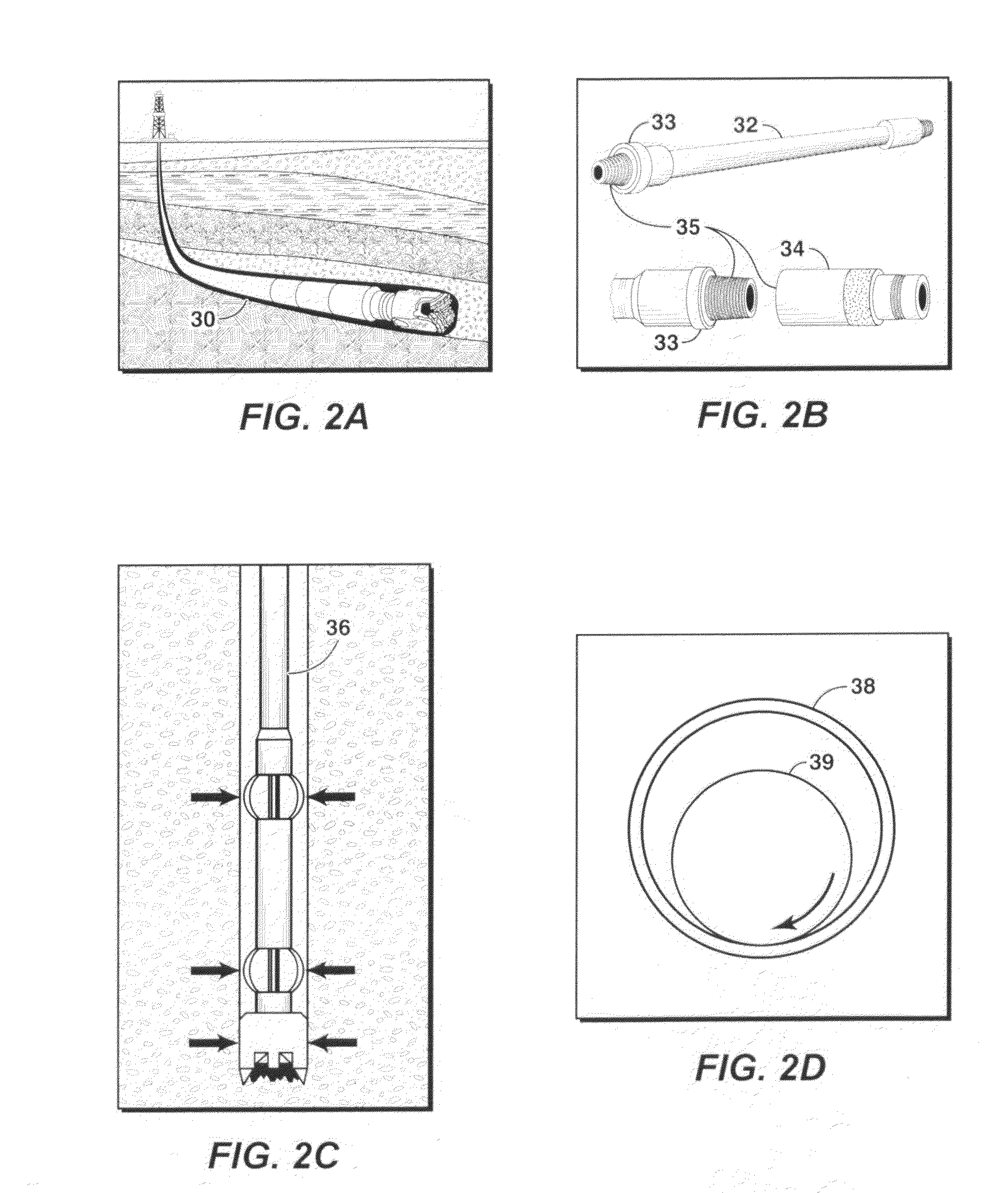
[0045]According to the present disclosure, an advantageous coated sleeved oil and gas well production device comprising: one or more cylindrical bodies, one or more sleeves proximal to the outer diameter or inner diameter of the one or more cylindrical bodies, and a coating on at least a portion of the inner sleeve surface, the outer sleeve surface, or a combination thereof of the one or more sleeves, wherein the coating is chosen from an amorphous alloy, a heat-treated electroless or electro plated based nickel-phosphorous composite with a phosphorous content greater than 12 wt %, graphite, MoS2, WS2, a fullerene based composite, a boride based cermet, a quasicrystalline material, a diamond based material, diamond-like-carbon (DLC), boron nitride, and combinations thereof.
[0046]A further aspect of the present disclosure relates to an advantageous coated sleeved oil and gas well production device comprising: an oil and gas well production device including one or more bodies with the proviso that the one or more bodies does not include a drill bit, one or more sleeves proximal to the outer surface or the inner surface of the one or more bodies, and a coating on at least a portion of the inner sleeve surface, the outer sleeve surface, or a combination thereof of the one or more sleeves, wherein the coating is chosen from an amorphous alloy, a heat-treated electroless or electro plated based nickel-phosphorous based composite with a phosphorous content greater than 12 wt %, graphite, MoS2, WS2, a fullerene based composite, a boride based cermet, a quasicrystalline material, a diamond based material, diamond-like-carbon (DLC), boron nitride, and combinations thereof.
[0047]A still further aspect of the present disclosure relates to an advantageous method of using a coated sleeved oil and gas well production device comprising: providing a coated oil and gas well production device including one or more cylindrical bodies with one or more sleeves proximal to the outer diameter or the inner diameter of the one or more cylindrical bodies, and a coating on at least a portion of t...

Problems solved by technology

First, the methods to apply the inventive coatings on production devices may require that the body be enclosed in a chamber.
This may be a very restrictive requirement for many oilfield components.
For example, the geometry of long pipe sections is cumbersome for such chambers.
This is also not likely to be very efficient since the surface area to be coated may be a small fraction of the total surface area of the main body.
The sleeve element may be subjected to high temperatures and other environmental conditions during the coating process that would cause damage to the other elements of the system.
The prior art does not disclose an efficient means to address these problems, and the inventive methods will enable the use of low-friction coatings in oil and gas well production devices.

Method used


Image

  • Coated sleeved oil and gas well production devices
  • Coated sleeved oil and gas well production devices
  • Coated sleeved oil and gas well production devices

Examples


example 1

Illustrative Example 1

[0267]DLC coatings were applied on 4142 steel substrates by vapor deposition technique. DLC coatings had a thickness ranging from 1.5 to 25 micrometers. The hardness was measured to be in the range of 1,300 to 7,500 Vickers Hardness Number. Laboratory tests based on ball on disk geometry have been conducted to demonstrate the friction and wear performance of the coating. Quartz ball and mild steel ball were used as counterface materials to simulate open hole and cased hole conditions respectively. In one ambient temperature test, uncoated 4142 steel, DLC coating and commercial state-of-the-art hardbanding weld overlay coating were tested in “dry” or ambient air condition against quartz counterface material at 300 g normal load and 0.6 m / sec sliding speed to simulate an open borehole condition. Up to 10 times improvement in friction performance (reduction of friction coefficient) over uncoated 4142 steel and hardbanding could be achieved in DLC coatings as shown...

example 2

Illustrative Example 2

[0272]In the laboratory wear / friction testing, the velocity dependence (velocity weakening or strengthening) of the friction coefficient for a DLC coating and uncoated 4142 steel was measured by monitoring the shear stress required to slide at a range of sliding velocity of 0.3 m / sec˜1.8 m / sec. Quartz ball was used as a counterface material in the dry sliding wear test. The velocity-weakening performance of the DLC coating relative to uncoated steel is depicted in FIG. 23. Uncoated 4142 steel exhibits a decrease of friction coefficient with sliding velocity (i.e. significant velocity weakening), whereas DLC coatings show no velocity weakening and indeed, there seems to be a slight velocity strengthening of COF (i.e. slightly increasing COF with sliding velocity), which may be advantageous for mitigating torsional instability, a precursor to stick-slip vibrations.

example 3

Illustrative Example 3

[0273]Multi-layered DLC coatings were produced in order to maximize the thickness of the DLC coatings for enhancing their durability for drill stem assemblies used in drilling operations. In one form, the total thickness of the multi-layered DLC coating varied from 6 μM to 25 μm. FIG. 24 depicts SEM images of both single layer and multilayer DLC coatings for drill stem assemblies produced via PECVD. An adhesive layer(s) used with the DLC coatings was a siliceous buffer layer.


PUM


Abstract

Provided are coated sleeved oil and gas well production devices and methods of making and using such coated sleeved devices. In one form, the coated sleeved oil and gas well production device includes an oil and gas well production device including one or more bodies and one or more sleeves proximal to the outer or inner surface of the one or more bodies, and a coating on at least a portion of the inner sleeve surface, outer sleeve surface, or a combination thereof, wherein the coating is chosen from an amorphous alloy, a heat-treated electroless or electro plated based nickel-phosphorous composite with a phosphorous content greater than 12 wt %, graphite, MoS2, WS2, a fullerene based composite, a boride based cermet, a quasicrystalline material, a diamond based material, diamond-like-carbon (DLC), boron nitride, and combinations thereof. The coated sleeved oil and gas well production devices may provide for reduced friction, wear, erosion, corrosion, and deposits for well construction, completion and production of oil and gas.

Description

CROSS-REFERENCE TO RELATED APPLICATIONS[0001]This application is a Continuation-in-Part of U.S. patent application Ser. No. 12 / 583,302, filed Aug. 18, 2009, and U.S. patent application Ser. No. 12 / 583,292, filed Aug. 18, 2009, and claims priority of U.S. Provisional Application Ser. No. 61 / 207,814, filed Feb. 17, 2009, and U.S. Provisional Application Ser. No. 61 / 189,530, filed Aug. 20, 2008, the contents of each are hereby incorporated by reference.FIELD[0002]The present disclosure relates to the field of oil and gas well production operations. It more particularly relates to the use of coated sleeved devices to reduce friction, wear, corrosion, erosion, and deposits in oil and gas well production operations. Such coated sleeved oil and gas well production devices may be used in drilling rig equipment, marine riser systems, tubular goods (casing, tubing, and drill strings), wellhead, trees, and valves, completion strings and equipment, formation and sandface completions, artificial...

Claims


Application Information

Patent Timeline
IPC IPC(8): E21B41/00E21B17/00
CPCE21B17/042E21B41/00E21B17/1085
Inventor BAILEY, JEFFREY ROBERTSBIEDIGER, ERIKA ANN OOTENBANGARU, NARASIMHA-RAO VENKATAOZEKCIN, ADNANJIN, HYUN-WOOERTAS, MEHMET DENIZAYER, RAGHAVANELKS, WILLIAM CURTISYEH, CHARLES SHIAO-HSIUNGBARRY, MICHAEL DAVIDHECKER, MICHAEL THOMASBANGARU, SWARUPA SOMA
Owner EXXONMOBIL UPSTREAM RES CO
Learn More