
Method and circuit for processing a resolver fault

a technology of resolver and circuit, applied in the direction of motor/generator/converter stopper, dynamo-electric converter control, instruments, etc., can solve problems such as vehicle shutdown

Active Publication Date: 2011-02-24
GM GLOBAL TECH OPERATIONS LLC
View PDF8 Cites 9 Cited by
  • Summary
  • Abstract
  • Description
  • Claims
  • Application Information

AI Technical Summary

Benefits of technology

The patent describes a method for detecting and addressing intermittent faults in a resolver used for monitoring the position of a rotor in a motor generator unit (MGU) used for propelling electric vehicles. The method allows the controller of the MGU to have sufficient time to "ride out" the resolver fault without shutting down the vehicle, resulting in a smooth transition from the resolver fault state to a normal operating state. The method uses an algorithm to detect the resolver fault, calculate the estimated position of the rotor, select the resolver fault state based on the duration of the fault, and control the output of the MGU accordingly. The technical effect of this patent is to provide a reliable and efficient method for addressing intermittent faults in the resolver of an MGU, ensuring smooth operation of the vehicle.

Problems solved by technology

Certain conventional vehicle control systems may utilize simple switch-debouncing procedures of the type known in the art, which may in turn cause the vehicle to shut down during a resolver fault in an attempt at preventing undesirable generation of motor torque during the duration of the resolver fault.

Method used


Image

  • Method and circuit for processing a resolver fault
  • Method and circuit for processing a resolver fault
  • Method and circuit for processing a resolver fault

Examples


Embodiment Construction

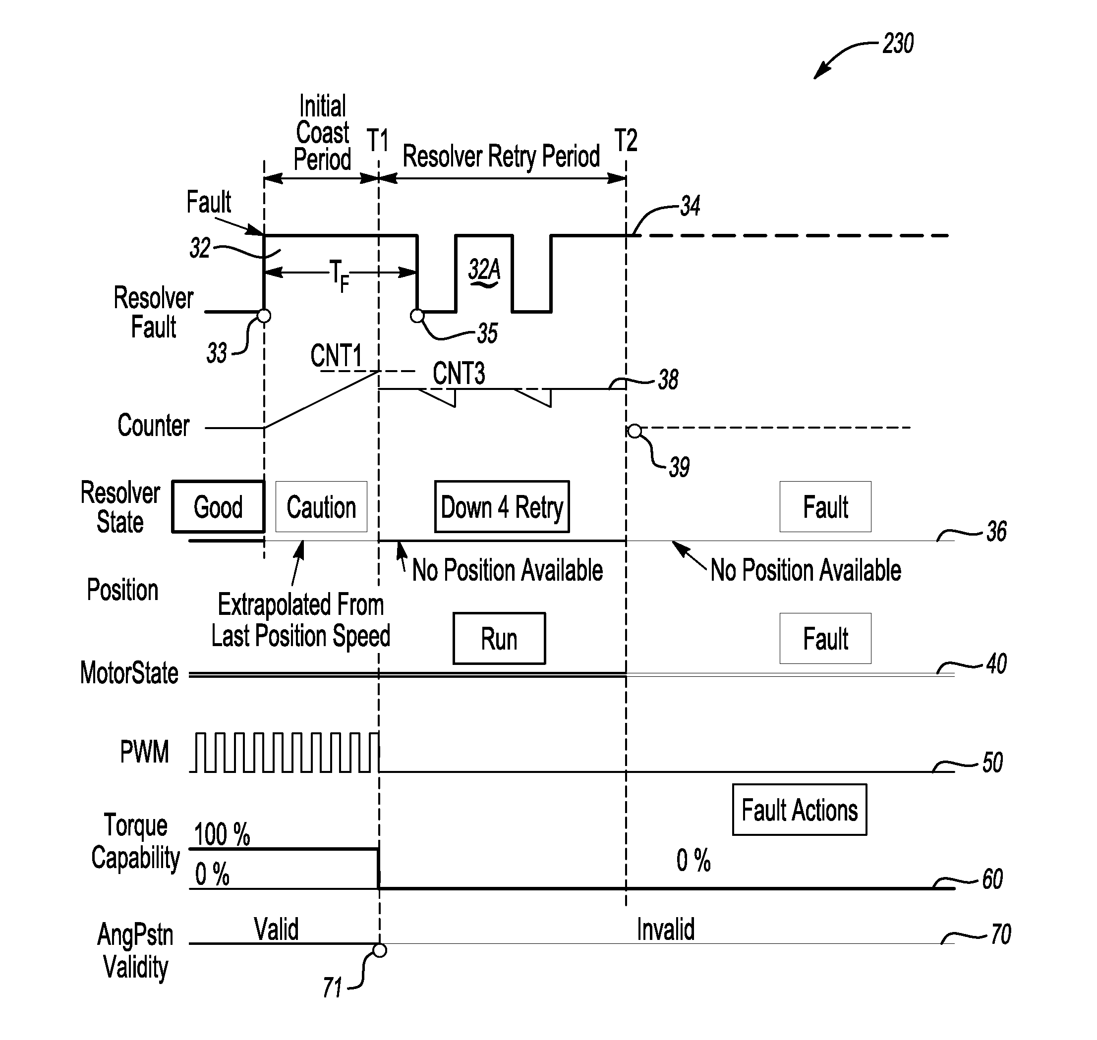
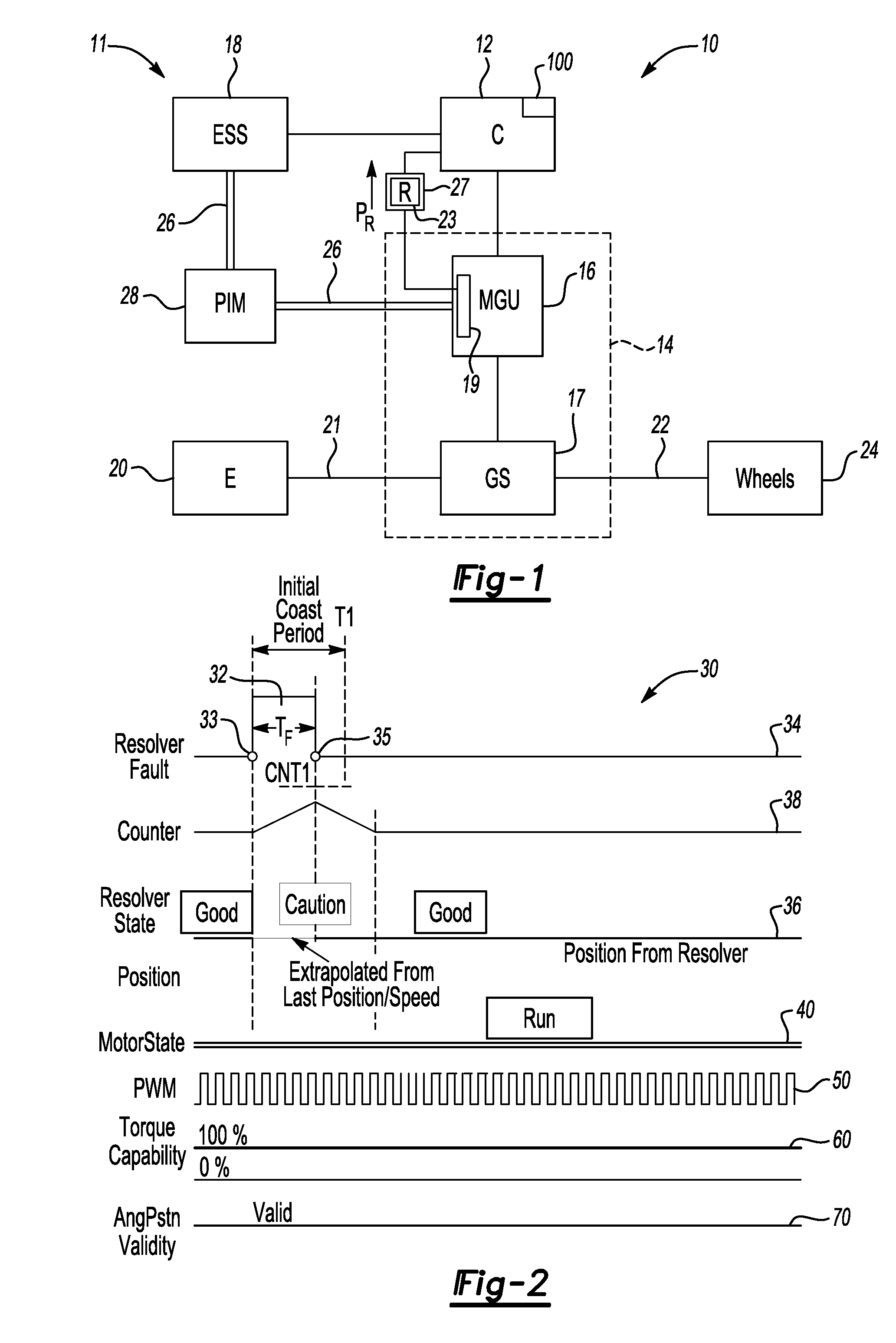
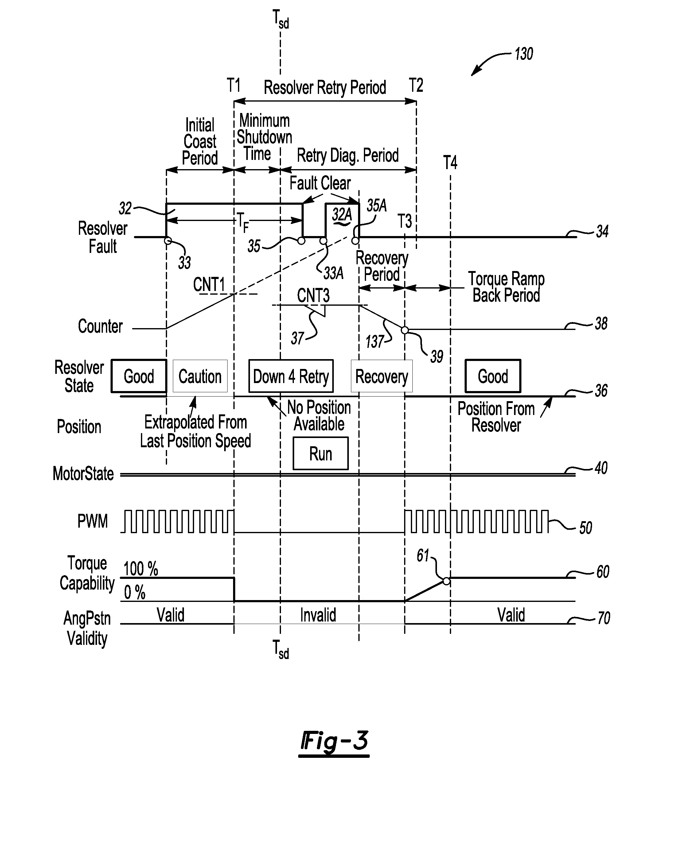
[0016]Referring to the drawings, wherein like reference numbers correspond to like or similar components throughout the several figures, FIG. 1 shows a vehicle10 having a motor control circuit 11, although the circuit may be used separately from the vehicle without departing from the intended inventive scope. Circuit 11 includes a controller 12 having an algorithm 100 adapted for executing the method of the present invention during a predetermined resolver fault condition, as will be described below with reference to FIGS. 2-6. The vehicle 10 includes a transmission 14 having at least one high-voltage electric motor / generator unit (MGU) 16 and at least one gear set (GS) 17.

[0017]The controller 12 may be configured as a digital computer generally including a CPU, and has sufficient memory for executing its required functions, such as read only memory (ROM), random access memory (RAM), electrically-programmable read only memory (EPROM), etc. The controller 12 may include a high-speed ...


PUM


Abstract

A method of processing a resolver fault in a motor generator unit (MGU) includes receiving a position signal from a resolver describing a measured angular position of a rotor of the MGU, determining the presence of the resolver fault using the position signal, and calculating or extrapolating an estimated rotor position when the resolver fault is determined. A predetermined resolver fault state may be determined using a measured duration of the resolver fault, and the MGU may be controlled using the estimated rotor position for at least a portion of the duration of the resolver fault. A motor control circuit is operable for processing the resolver fault using the above method, and may automatically vary a torque output or a pulse-width modulation (PWM) of the MGU depending on the duration of the resolver fault.

Description

TECHNICAL FIELD[0001]The present invention relates a method and a motor control circuit adapted for processing a motor / generator unit (MGU) resolver fault.BACKGROUND OF THE INVENTION[0002]In a high-voltage propelled vehicle such as a hybrid-electric vehicle (HEV) or an electric vehicle (EV), an onboard energy storage system (ESS) provides a source of at least a portion of the necessary propulsive power. An internal combustion engine may be shut off or selectively powered down when the vehicle is idling in order to conserve fuel. Energy may be captured during a regenerative braking event in order to recharge the ESS, and thereby further optimize fuel economy. The ESS may be configured as a bank of battery cells that collectively store a relatively high voltage, e.g., 300 volts or higher. This voltage is transmitted to one or more high-voltage devices, including one or more motor / generator units (MGU), via a high-voltage bus and a power inverter module (PIM).[0003]To ensure optimal pe...

Claims


Application Information

Patent Timeline
Patent Type & Authority Applications(United States)
IPC IPC(8): H02P6/16
CPCG01D5/24476G01D3/08
Inventor WANG, WEI D.BAE, BON HOWEST, STEPHEN T.SCHROEDER, RICK H.
Owner GM GLOBAL TECH OPERATIONS LLC
Learn More