Coil decoupling for an RF coil array

a phased array and coil array technology, applied in the field of phased arrays of radio frequency (rf) coils for magnetic resonance imaging, can solve the problems of inability to decouple by, inability to achieve simultaneous improvement of both of these parameters, and inability to achieve design compromises, etc., to achieve less space, reduce the resistance of parallel resonant circuits, and improve efficiency

Active Publication Date: 2011-02-24
DEERFIELD IMAGING INC
View PDF8 Cites 30 Cited by
  • Summary
  • Abstract
  • Description
  • Claims
  • Application Information

AI Technical Summary

Benefits of technology

[0048]The new design is more efficient and takes less space than traditional arrangements for de-coupling adjacent and non-adjacent coil elements by reducing the resistance of parallel resonant circuit of preamplifier decoupling network which uses the built in inductor of preampli

Problems solved by technology

As is well known, adjacent coil elements are typically de-coupled by different methods, including geometry, capacitive, and inductive de-coupling, but it is not always possible to de-couple by these methods therefore the parallel resonant circuit with lower input impedance preamplifier in each coil is necessar

Method used


Image

  • Coil decoupling for an RF coil array
  • Coil decoupling for an RF coil array
  • Coil decoupling for an RF coil array

Examples


Embodiment Construction

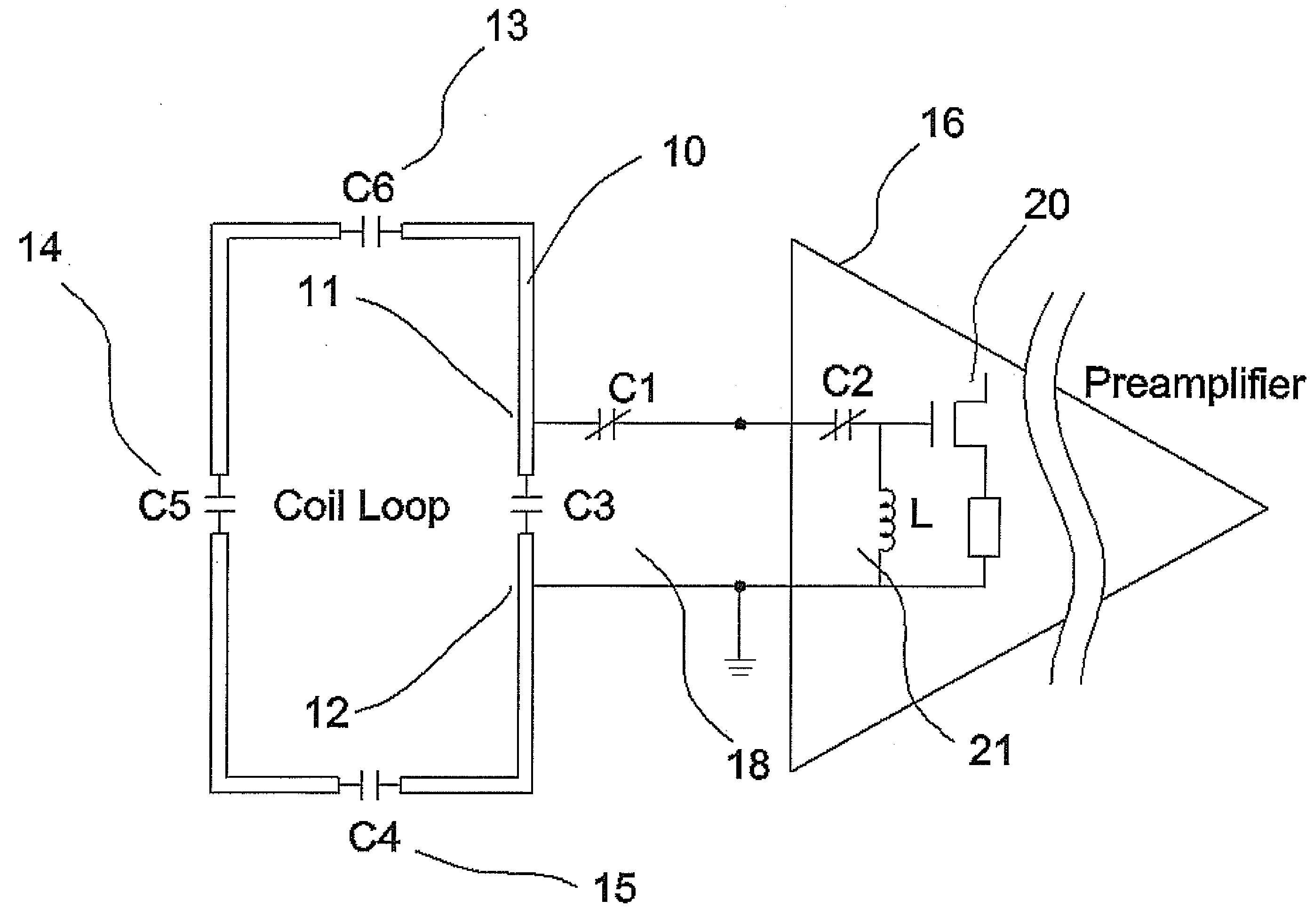
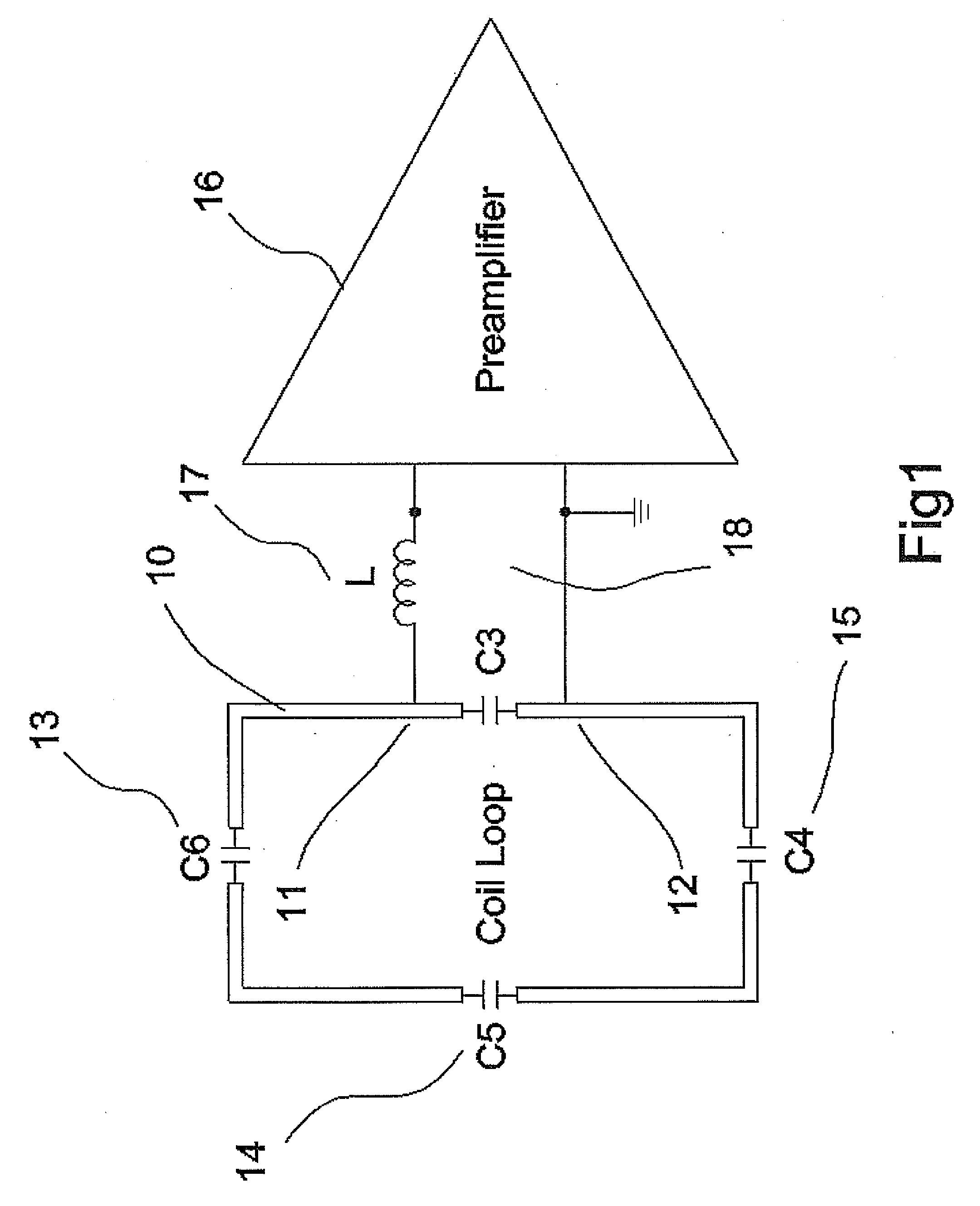
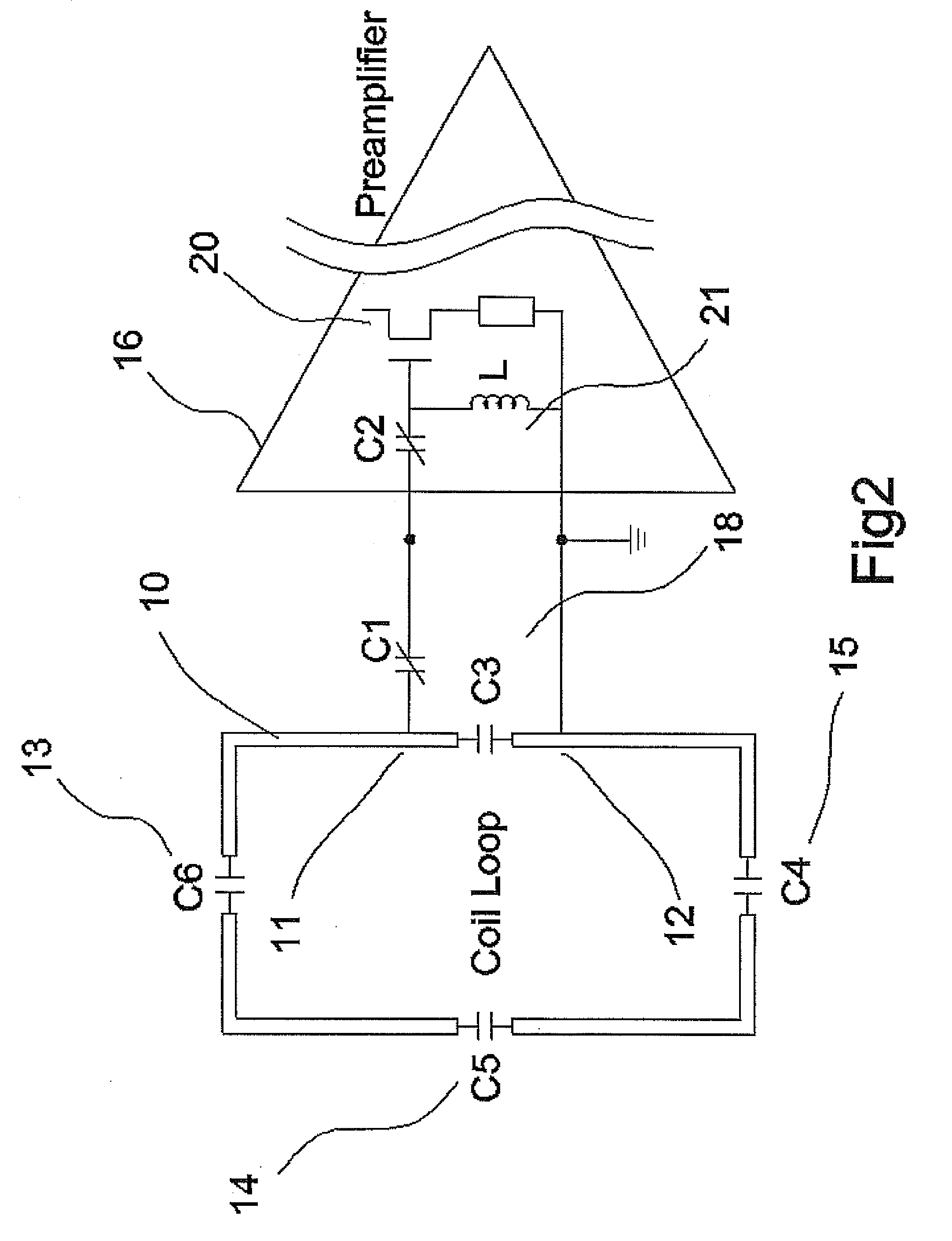
[0053]In FIG. 1 is shown a single coil of an RF phased coil array for use in a magnetic resonance system for detecting NMR signals from a subject. The array includes a series of RF coil elements arranged in an array for receiving RF signals from the subject, each of the coil elements having a conductive loop 10 with a pair of ends 11 and 12 across which the signal is applied. The coil includes a number of components in series as indicated at 13, 14 and 15 arranged for frequency tuning to the magnetic resonance frequency. The components 13, 14 and 15 are well known to persons skilled in the art of coil design so that further description is not required.

[0054]The coil element has a pre-amplifier circuit 16 for receiving a signal from the pair of ends 11 and 12 of the coil element 10 for amplification of the signal to submit to a signal analysis system

[0055]There is also provided a preamplifier decoupling circuit 18 which is arranged to provides a high impedance across the ends 11 and ...


PUM


Abstract

An MRI phase RF coil array includes a plurality of separate RF coil elements where each coil element has a pre-amplifier circuit with a conditioning circuit in advance of the transistor including an inductor and capacitors connected across the input of preamplifier. Each of the coil elements has a preamplifier decoupling parallel resonant circuit for generating a tuned high impedance across the ends of the coil so as to inhibit coupling in the coil from signals in adjacent and non-adjacent coils of the array. The decoupling circuit comprises a fixed first capacitor across the ends, a second variable capacitor in one of the leads, a further capacitor in the conditioning circuit, all of which define a capacitance which co-operates with the inductance defined by the inductor of the conditioning circuit of preamplifier to form the parallel resonant circuit to generate the high impedance.

Description

[0001]This invention relates to an RF coil array for use in a magnetic resonance system for detecting MR signals.BACKGROUND OF THE INVENTION[0002]The following relates to phased arrays of radio frequency (RF) coils for magnetic resonance imaging, and will be described with particular reference thereto. It finds application more generally in conjunction with magnetic resonance imaging, magnetic resonance spectroscopy, and other magnetic resonance applications.[0003]Many techniques increasingly employ arrays of surface coils to act as a transmit and receive antenna. Each surface coil of the array typically includes a conductive RF loop, and required electronic components providing required features including frequency tuning the magnetic resonance frequency and matching to required impedance (e.g. 50 ohm); a pre-amplifier for amplifying the received signal from the subject in the magnet; coil detuning during the transmit phase; coil decoupling from adjacent and non-adjacent coil eleme...

Claims


Application Information

Patent Timeline
IPC IPC(8): G01R33/44
CPCG01R33/3415G01R33/365G01R33/3628
Inventor ZHU, HAOQIN
Owner DEERFIELD IMAGING INC
Why Eureka
Try Eureka