Thin film forming method and thin film stack

Inactive Publication Date: 2011-03-03
KONICA MINOLTA INC
View PDF2 Cites 6 Cited by
  • Summary
  • Abstract
  • Description
  • Claims
  • Application Information

AI Technical Summary

Benefits of technology

[0031]The thin film forming method by which the uniform quality thin film can be stably formed at high pr

Problems solved by technology

Therefore, the treatment system is necessarily made vacuum to enough degree so that the mechanical device units to be equipped in the film forming apparatus should be made to large-scale such as a large treatment chamber and a large vacuum pump, and complicated works under highly reduced pressure are required.
Moreover, the various conditions such as the diameter and the width of the rolled substrate and the volume of the raw materials for thin film formation are limited by the properties of these apparatus and the device units.
On the other side, however, the cost of the apparatus such as the electrodes is high.
However, there is the possibility of concentrated arc discharge of large current in such the case.
Furthermore, the foregoing electrodes have problems, since the forgoing electrodes are fixed electrodes, that the surface of the electrodes are gradually contaminated because they are always exposed to the

Method used


Image

  • Thin film forming method and thin film stack
  • Thin film forming method and thin film stack
  • Thin film forming method and thin film stack

Examples


Example

Example 1

Preparation of Thin Film Stack

[Preparation of Thin Film Stack 1: Invention]

[0169][Film Forming Process]

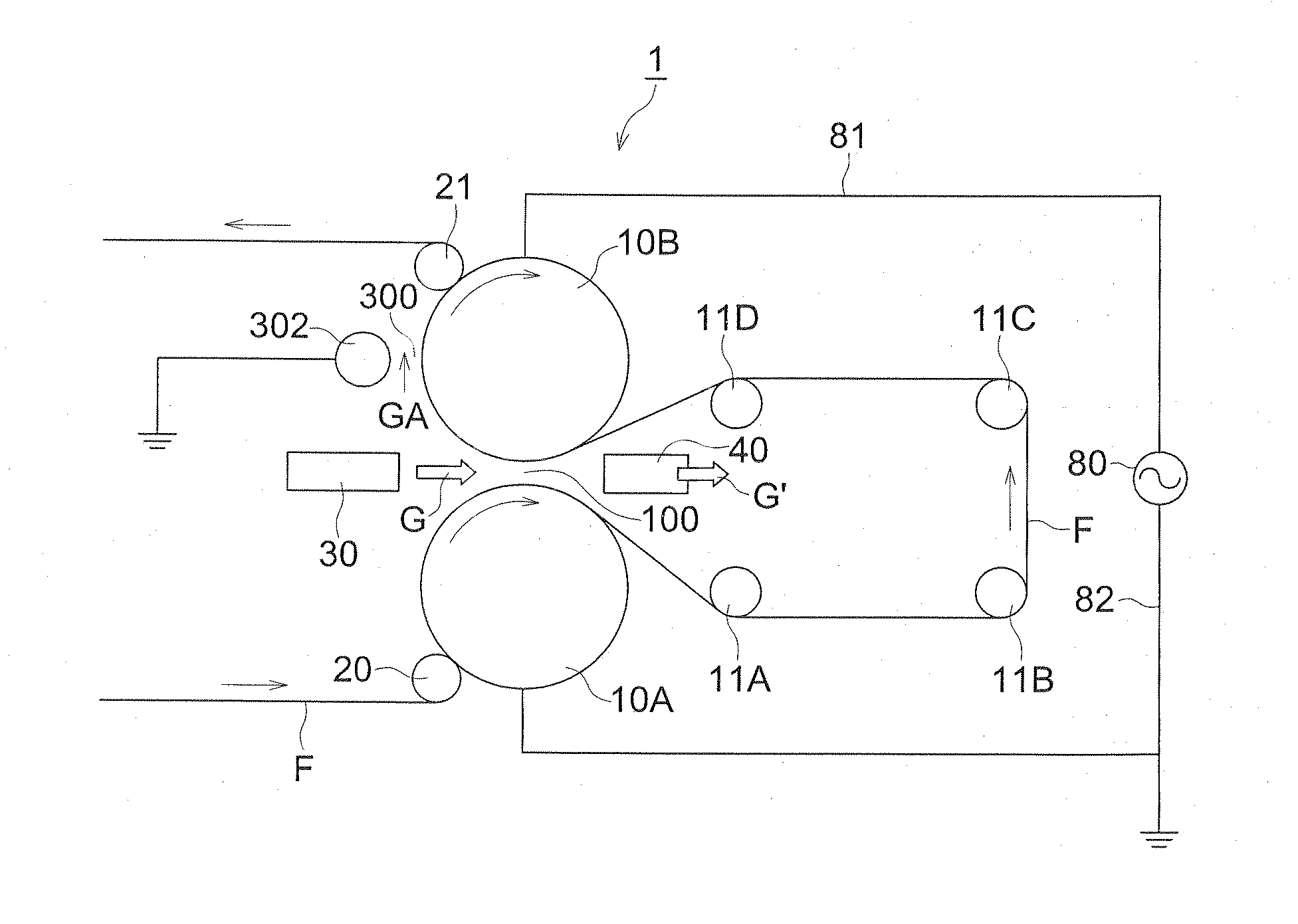
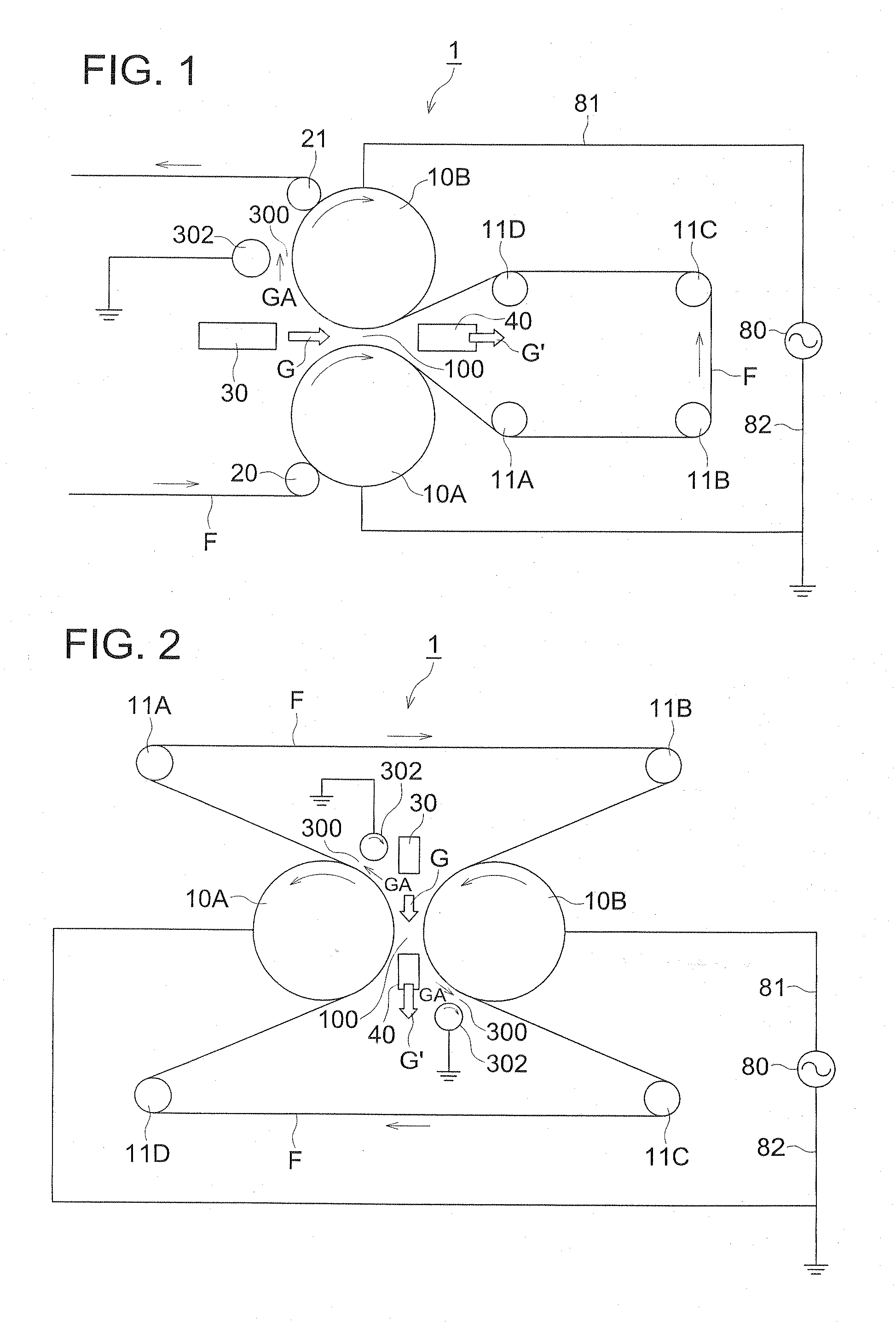
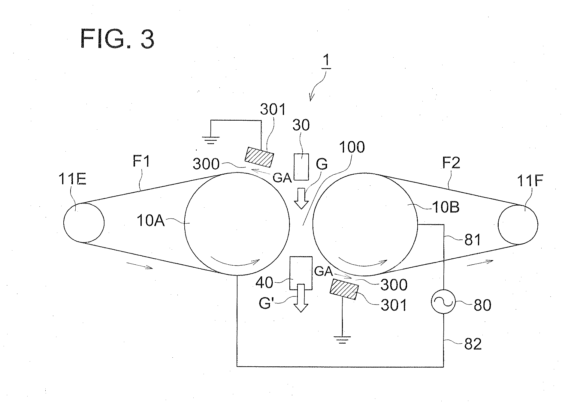
[0170]Rolled poly(ethylene terephthalate) film with a thickness of 100 μm as the substrate F was twice passed through the discharging space 100 of the atmospheric pressure plasma discharge treating apparatus shown in FIG. 5 (the film forming process: voltage applying system B using the electric field generated by overlapping the first electric field and the second electric field, the post-treating process: voltage applying system A using the single power source only) having the gas supplying means 30 shown in FIG. 8 under the following discharging conditions to form a functional thin film (an antireflection film) having a thickness of 100 nm.

[0171]The roller electrodes 10A and 10B were each prepared by using a mother material of jacket roller made from titanium ally T64 having a cooling means by cooling water, on which a high density and high adhesive alumina film was spat...


PUM

PropertyMeasurementUnit
Frequencyaaaaaaaaaa
Frequencyaaaaaaaaaa
Frequencyaaaaaaaaaa

Abstract

A thin film forming method by a plasma discharging treatment under atmospheric pressure with a thin film forming apparatus which has a first discharging space for forming a functional thin film on a substrate, and a second discharge space for post-treating the substrate which formed the thin film. The first discharge space has a roller electrodes pair. The thin film forming method includes, a film forming process at the first discharge space which includes the steps of transporting the substrate by the roller electrodes; supplying discharging gas and thin film forming gas into the first discharging space; and generating a high frequency electric field between the roller electrodes. The post-treatment process includes the steps of introducing the substrate on which the functional film is formed; and supplying a discharging gas and post-treatment gas between the facing electrodes; and, generating a high frequency electric field between the facing electrode and the roller electrode.

Description

[0001]This application is a continuation-in-part application of International Application PCT / JP2009 / 050819 filed Jan. 21, 2009, which claims the priority of Japanese Application JP 2008-037356 filed Feb. 19, 2008.TECHNICAL FIELD[0002]This invention relates to a method for forming a thin film by a plasma treatment system under the atmospheric pressure or a pressure near atmospheric pressure.TECHNICAL BACKGROUND[0003]Recently, various materials each composed of a substrate and a highly functional thin film such as an electrode film, dielectric protective film and a semiconductor film are frequently used in various products such as a LSI, semiconductor, displaying device, magnetic recording device and photo-electrical converter device.[0004]For forming such the highly functional thin films, a wet film forming method typified by a coating method or a vacuum deposition method, a spattering method, an ion beam method, an ion plating method and a plasma-chemical vapor deposition (CVD) met...

Claims


Application Information

Patent Timeline
IPC IPC(8): C23C16/507B32B9/00
CPCC23C16/401C23C16/45563C23C16/509H01J37/32825C23C16/56H01J37/32082H01J37/3277C23C16/545Y10T428/31663
Inventor OISHI, KIYOSHI
Owner KONICA MINOLTA INC
Why Eureka
Try Eureka