PH2OCP - portable water and climatic production system

Active Publication Date: 2011-03-10
7142871 CANADA
View PDF22 Cites 52 Cited by
  • Summary
  • Abstract
  • Description
  • Claims
  • Application Information

AI Technical Summary

Benefits of technology

[0030]The condenser coil assembly is a series of fined coils/piping with a fan that draws outside air across the coil assembly. As the refrigerant passes through the condenser coil assembly and the outside air passes across the coil fins, the heat from the refrigerant is rejected to the outside air which causes the refrigerant to condense from a gas to a liquid state. The high-pressure, high-temperature liquid then reaches the refrigerant flow metering device. The refrigerant flow metering device is the manager of the system and directed by input from the PLC controller panel. By sensing the temperature &/or pressure of the evaporator cooling coils located in the condensation process section, it allows liquid refrigerant to pass through a very small orifice, which causes the refrigerant to expand to a low-pressure, low-temperature gas. This cold refrigerant flows to the evaporator. The evaporator

Problems solved by technology

This vital resource is becoming a priceless commodity due to the ever increasing global demands and population requirements for reusable, clean and potable water.
Though effective, this technological solution has also proven to be costly both on the transformation and production of potable water as well as the high cost of system purchase and maintenance.
Whether these type systems deliver sanitized water or are limited in their processing and production capabilities, nevertheless, they still require a water source which may not always be existent and or available for use, in order to deliver decontaminated filtered water

Method used


Image

  • PH2OCP - portable water and climatic production system
  • PH2OCP - portable water and climatic production system
  • PH2OCP - portable water and climatic production system

Examples


Embodiment Construction

[0042]The description which follows and the embodiments described therein are provided by way if illustration of an example, or examples of particular embodiments of principles and aspects of the present invention. These examples are provided for the purpose of explanation and not of limitation, of those principles of the invention.

[0043]In the description that follows, like parts are marked throughout the specification and the drawings with the same respective reference numerals.

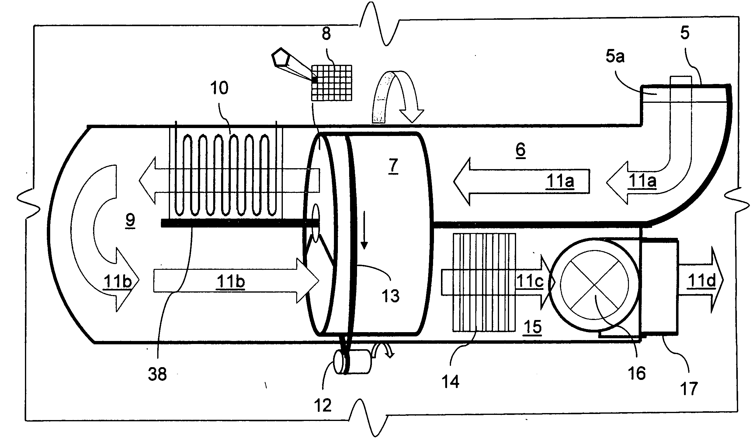
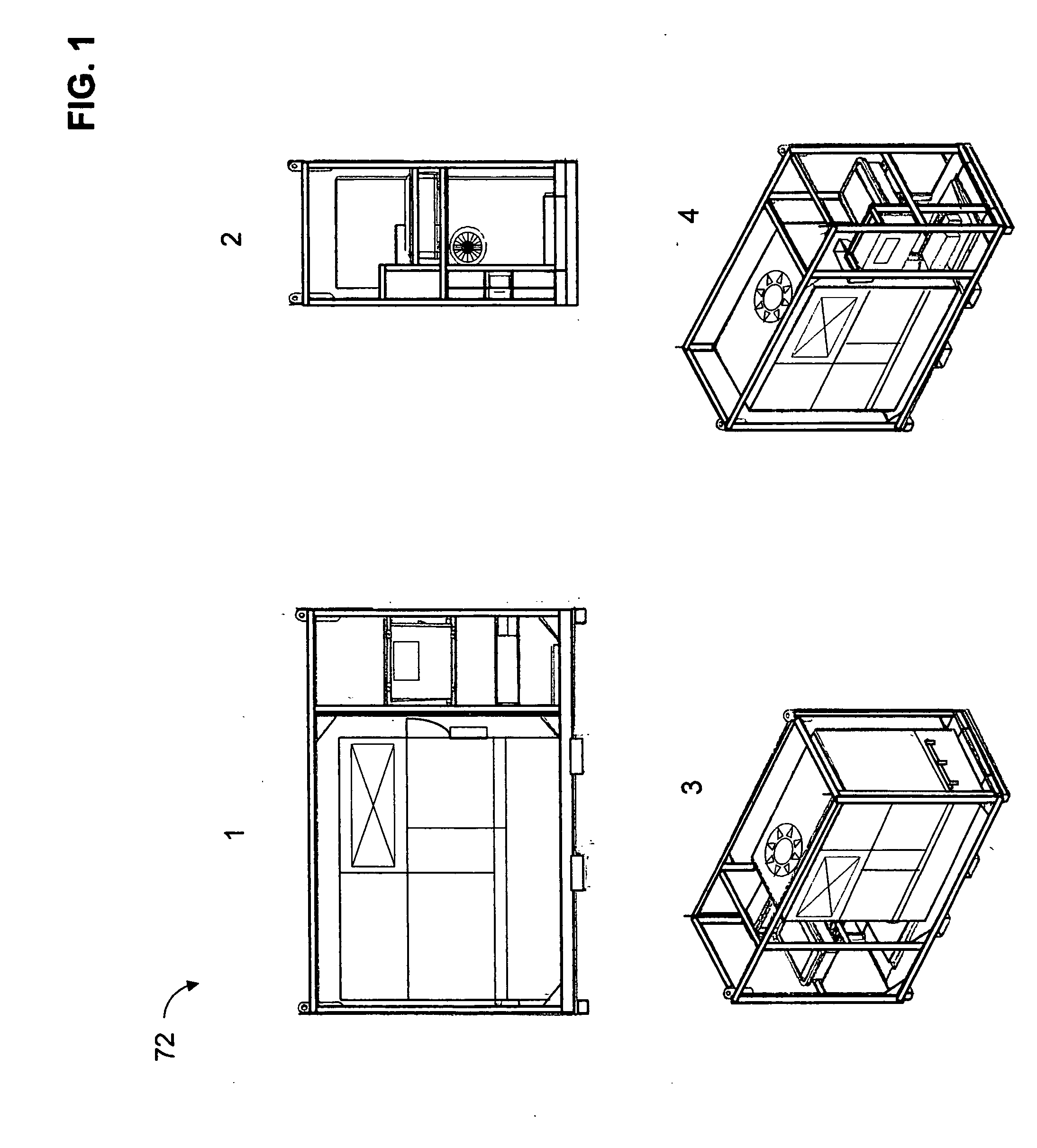
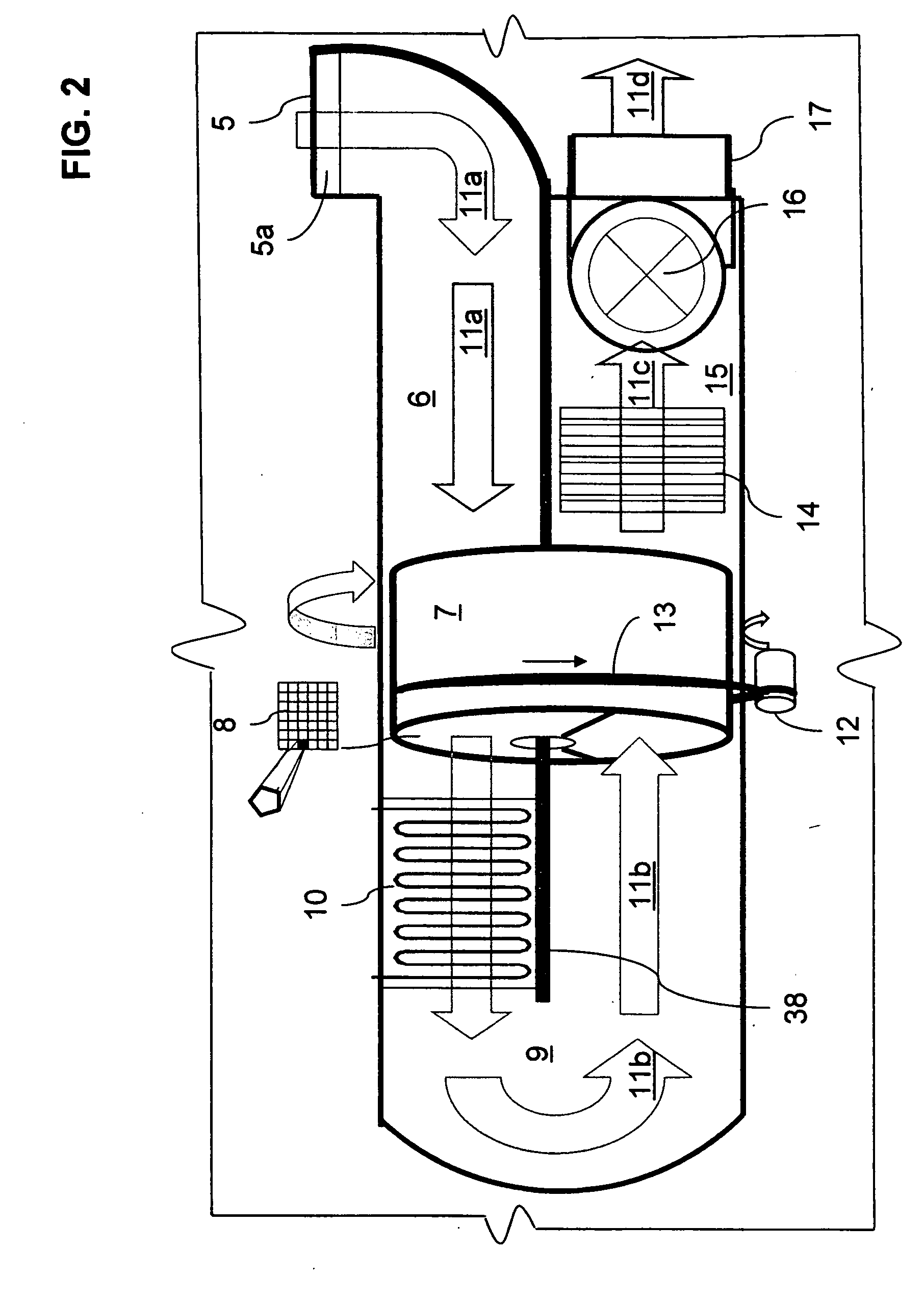
[0044]With regards to the nomenclature, the term “PH2OCP” as it is used throughout the specification identifies the Portable Water and Climatic Production system FIGS. 3, 4, 7, 8, 9, which will be designated generally with reference numeral 72FIG. 1. The PH2OCP system herein includes various components and main sub-systems such as; desiccant rotor or wheel technology, microwave reactivation system, the air treatment and conditioning system as well as all parts, modules and electrical components. Referring t...


PUM

PropertyMeasurementUnit
Diameteraaaaaaaaaa
Energyaaaaaaaaaa
Humidityaaaaaaaaaa

Abstract

The present invention “PH2OCP” relates to a portable water and climatic production system. In the preferred embodiment, the system uses a combination of heating coils assemblies, cooling coils and more specifically the desiccant rotor technology for the extraction, collection of water vapor molecules from the air stream and transformation in to condensate for the production of clean filtered potable water.
The portable water and climatic production system or “PH2OCP” is designed to operate and produce water in a wide range of global climatic conditions, including the most arid of environments. This is made possible due to the highly effective performance capabilities of the desiccant rotor technology in the extraction of water vapor molecules from any existing ambient air.
The desiccant technology is designed in the “PH2OCP” to operate in combination with the microwave reactivation system in the regeneration or reactivation section and cooling coils assembly located in the condensation section.

Description

CROSS-REFERENCE TO RELATED APPLICATION[0001]This non-provisional utility application claims priority over the provisional patent application numbered: U.S. 61 / 276,038Title: PH2OCP—Portable Water and Climatic Production SystemFiling Date Sep. 8, 2009Confirmation No.: 6682[0002]This non-provisional utility application also makes reference in the SPECIFICATION to a previously submitted non-provisional utility application which claimed priority over the provisional patent application number: U.S. 61 / 268,004Title: Microwave Reactivation System for Standard and Explosion-ProofDehumidification SystemFiling Date: Jun. 8, 2009Confirmation No.: 8793STATEMENT REGARDING FEDERALLY SPONSORED RESEARCH OR DEVELOPMENT[0003]Not ApplicableREFERENCE TO SEQUENCE LISTING, A TABLE, OR A COMPUTER PROGRAM LISTING COMPACT DISC APPENDIX[0004]Not ApplicableBACKGROUND OF THE INVENTION[0005]The existence of moisture and humidity in all matter that surrounds us, in the air we breathe and in our environment play a...

Claims


Application Information

Patent Timeline
IPC IPC(8): F25D17/06B01D53/06F25D31/00F25D21/00H05B6/64
CPCB01D53/002B01D53/06B01D2253/106B01D2253/108B01D2257/80F24F2003/1458B01D2259/4541F24F2203/1032H05B6/80F24F3/1423B01D2259/40094
Inventor CAGGIANO, MARIO
Owner 7142871 CANADA
Why Eureka
Try Eureka