
Ammonia generating method and apparatus therefor

a technology of ammonia generating method and apparatus, which is applied in the direction of combustible gas production, separation processes, bulk chemical production, etc., can solve the problems of affecting the operation of the gasification furnace, difficult to use the gasification furnace continuously for a long period of time, and the gasification reaction to reach a high temperature, so as to prolong the life of the refractory brick, reduce the overall cost of the apparatus, and avoid the effect of affecting the operation

Inactive Publication Date: 2011-03-17
MITSUBISHI HEAVY IND LTD
View PDF5 Cites 7 Cited by
  • Summary
  • Abstract
  • Description
  • Claims
  • Application Information

AI Technical Summary

Benefits of technology

[0013]Because an ammonia generating apparatus of the present invention has a gasification furnace into which coal and air are introduced, constituted so as to perform partial oxidation to gasify the coal, a desulfurizing apparatus constituted so as to desulfurize the gas generated by the gasification furnace, a shift reactor constituted so as to convert carbon monoxide present in the gas exhausted from the desulfurizing apparatus to carbon dioxide, a carbon dioxide scrubber constituted so as to remove carbon dioxide present in the gas exhausted from the shift reactor, a denitrification apparatus constituted so that by removing nitrogen present in the gas exhausted from the carbon dioxide scrubber, the molar ratio between nitrogen and hydrogen present in the gas is adjusted to approximately 1:3, and an ammonia generator that generates ammonia by causing a reaction between the nitrogen and hydrogen present in the gas exhausted from the denitrification apparatus, the oxygen concentration when the coal is combusted is reduced and, compared to the case of using oxygen to gasify coal, the temperature of the gasification reaction in the gasification furnace is low. As a result, it is possible to extend the life of the refractory brick inside the gasification furnace. Also, there is no melting of ashes and the like generated in the processing of the coal and adhesion thereof to the walls of the gasification furnace, so that operation of the gasification furnace is not hindered. The result is that, according to the present invention, it is possible to operate the gasification furnace continuously for a long period of time.
[0014]Also, because air is used to gasify the coal, the nitrogen present in the air can be used in the subsequent generation of ammonia, without introduction of nitrogen into the gas as was conventionally done.
[0015]Additionally, although in the past oxygen was used to gasify coal, thereby necessitating oxygen generating plant equipment for supplying oxygen, with the present invention because air is used to gasify coal, the need to provide oxygen generating plant equipment is eliminated, thereby enabling a reduction in the overall cost of the apparatus.
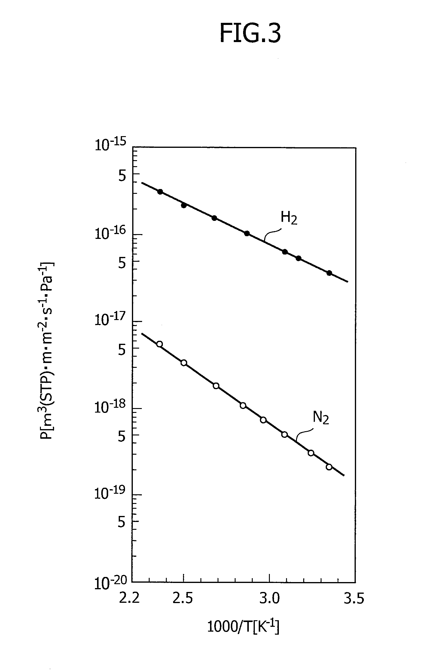
[0016]According to an ammonia generating apparatus of the present invention, because the denitrification apparatus may be constituted so as to remove nitrogen using a gas-separating membrane, it is possible to use the difference in permeating speed in the gas-separating membrane between nitrogen and hydrogen to separate nitrogen and hydrogen so as to adjust the molar ratio between nitrogen and hydrogen. Also, because the constitution makes use of a membrane, it is possible to achieve a simpler constitution for the apparatus. Also, in this constitution because there is a reduction of the pressure of the nitrogen and the hydrogen that pass through the gas-separating membrane, it is necessary to raise the pressure when generating ammonia.
[0017]According to an ammonia generating apparatus of the present invention, because the denitrification apparatus may be constituted so as remove nitrogen using an adsorbing material, it is possible to adjust the molar ratio between nitrogen and hydrogen by removing nitrogen from the gas without a reduction in the pressure of the hydrogen.
[0018]Because an ammonia generating method of the present invention includes a step of gasifying coal by introducing coal and air and causing partial oxidation, a step of desulfurizing the gas generated by the gasification step, a step of converting carbon monoxide present in the gas to carbon dioxide, a step of removing carbon dioxide present in the gas, a step of adjusting the molar ratio between nitrogen and hydrogen present in the gas to approximately 1:3 by removing nitrogen present in the gas, and a step of generating ammonia by causing a reaction between nitrogen and hydrogen present in the gas, the oxygen concentration when the coal is combusted is reduced and, compared to the case of using oxygen to gasify coal, the temperature of the gasification reaction in the gasification furnace is low. As a result, it is possible to extend the life of the refractory brick inside the gasification furnace. Also, there is no melting of ashes and the like generated in the processing of the coal and adhesion thereof to the walls of the gasification furnace, so that operation of the gasification furnace is not hindered. The result is that, according to the present invention, it is possible to operate the gasification furnace continuously for a long period of time.

Problems solved by technology

However, if oxygen is used when performing gasification of coal as described above in the conventional art, the oxygen concentration when the coal is partially oxidized is high, causing the gasification reaction in a gasification furnace to reach a high temperature.
The result of this is that the refractory brick in the gasification furnace reaches the end of its service life early, making it difficult to use the gasification furnace continuously for a long period of time.
Additionally, when the gasification reaction in the gasification furnace reaches a high temperature, ashes and the like generated in the processing of the coal melt and adhere to the walls of the gasification furnace, thereby creating the problem of hindering operation.
Also, in a constitution in which oxygen is used in the gasification of coal, it is necessary to have equipment for supplying oxygen to the gasification furnace, leading to the problem of high cost for the overall apparatus.

Method used


Image

  • Ammonia generating method and apparatus therefor
  • Ammonia generating method and apparatus therefor
  • Ammonia generating method and apparatus therefor

Examples


first embodiment

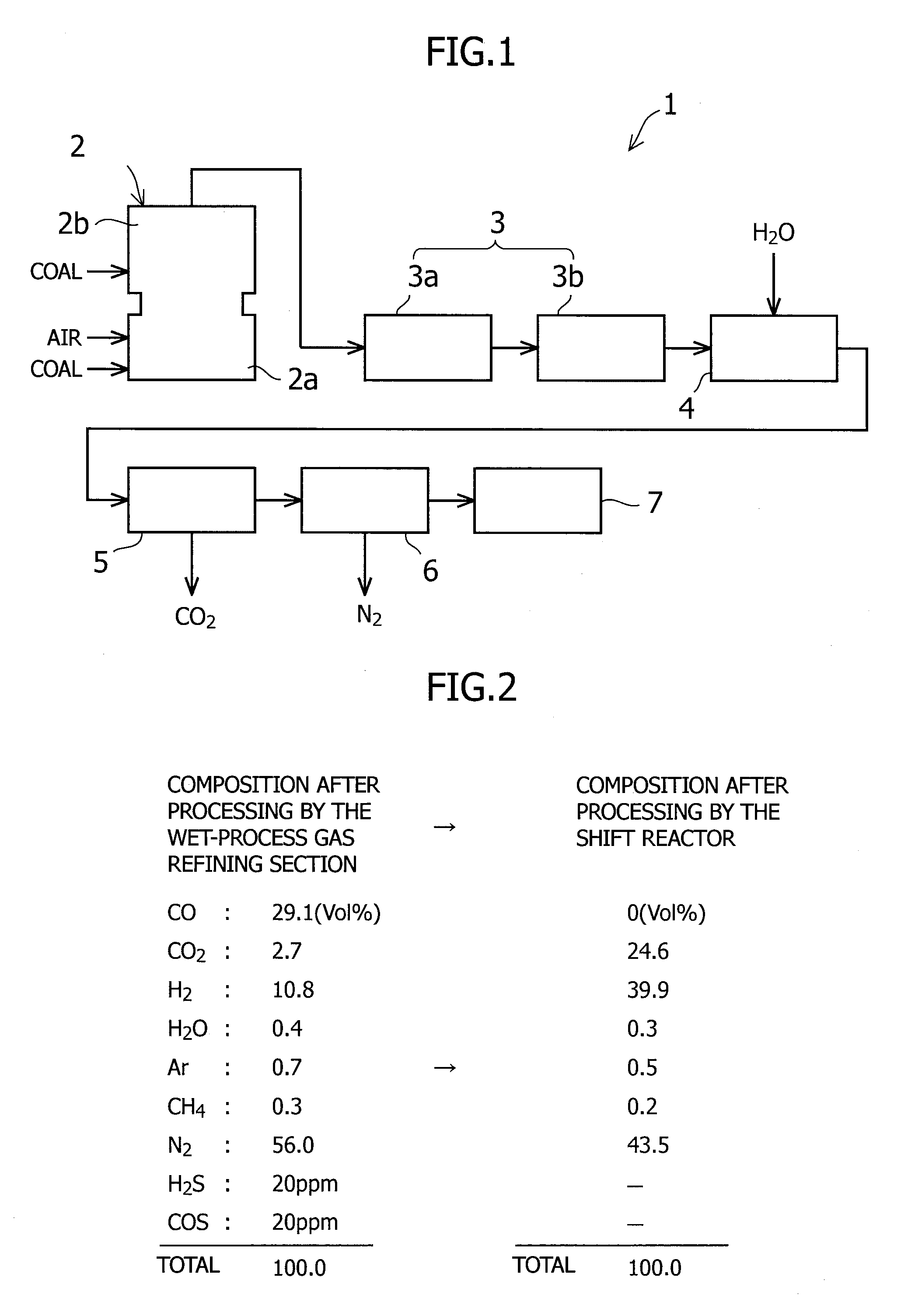
[0027]The first embodiment of an ammonia generating apparatus according to the present invention is described below with reference made to the accompanying drawings. FIG. 1 is a block diagram showing an ammonia generating apparatus according to this embodiment of the present invention.

[0028]As shown in FIG. 1, the ammonia generating apparatus 1 of this embodiment is provided with a gasification furnace 2, a desulfurizing apparatus 3, a shift reactor 4, a carbon dioxide scrubber 5, a denitrification apparatus 6, and an ammonia generator 7.

[0029]The gasification furnace 2 is an air-blowing type of gasification furnace, which is constituted by a combustion chamber (combustor) 2a and a gasification chamber (reductor) 2b. The gasification furnace 2 is arranged so as to combust coal, air and char (not illustrated) that are introduced into the combustion chamber 2a at a high temperature. In addition to introducing more coal into the gasification chamber 2b, the gasification furnace 2 makes...

second embodiment

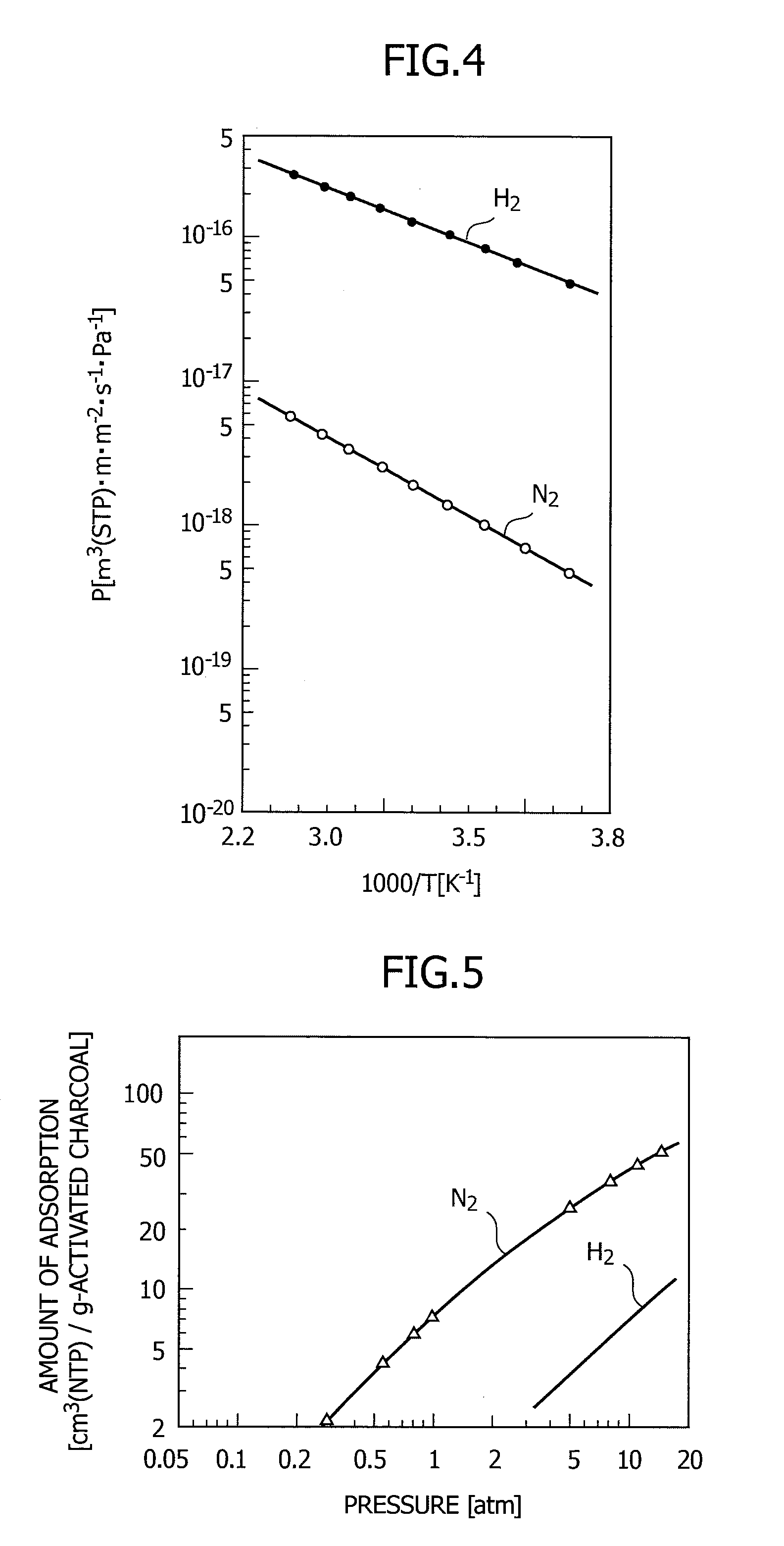
[0053]The second embodiment of an ammonia generating apparatus according to the present invention is described below with reference to the accompanying drawings. FIG. 5 is a graph showing the adsorption equilibrium of hydrogen and nitrogen in activated charcoal.

[0054]In the second embodiment, the denitrification apparatus 6 is constituted to remove nitrogen by using an adsorbing material. Activated charcoal, MS5A (5 A molecular sieve), MA4A (4 A molecular sieve), or activated alumina or the like is used as the adsorbing material.

[0055]FIG. 5 shows the adsorption equilibrium of nitrogen and hydrogen in activated charcoal. As shown in FIG. 5, if hydrogen and nitrogen are compared, the amount of adsorption of hydrogen is higher. Therefore, if activated charcoal is used as an adsorbing material, it is possible to adjust the molar ratio between nitrogen and hydrogen using the difference in the adsorption amounts of nitrogen and hydrogen. In this embodiment, the denitrification apparatus ...


PUM

PropertyMeasurementUnit
temperatureaaaaaaaaaa
pressureaaaaaaaaaa
temperatureaaaaaaaaaa

Abstract

An object of the present invention is to provide an ammonia generating method and apparatus that can be operated continuously for a long period of time, and that reduces the cost.The present invention has a gasification furnace 2 into which coal and air are introduced, constituted to perform partial oxidation to gasify the coal; a desulfurizing apparatus 3 constituted to desulfurize the gas generated by the gasification furnace 2; a shift reactor 4 constituted to convert carbon monoxide present in the gas exhausted from the desulfurizing apparatus 3 to carbon dioxide; a carbon dioxide scrubber 5 constituted to remove carbon dioxide present in the gas exhausted from the shift reactor 4; a denitrification apparatus 6 constituted so that, by removing nitrogen present in the gas exhausted from the carbon dioxide scrubber 5, the molar ratio between nitrogen and hydrogen present in the gas is adjusted to approximately 1:3; and an ammonia generator 7 that generates ammonia by causing a reaction between the nitrogen and hydrogen present in the gas exhausted from the denitrification apparatus 6.

Description

BACKGROUND OF THE INVENTION[0001]The present invention relates to an ammonia generating method, and in particular, relates to a method and apparatus for generating ammonia from coal.BACKGROUND ART[0002]In recent years, various plants have been constructed for the purpose of making ammonia, a typical type thereof being one that makes ammonia from coal. In the past, when synthesizing ammonia from coal, oxygen is first used to gasify the coal, thereby generating carbon monoxide (CO) and hydrogen gas and the like. After that, the carbon monoxide is converted to hydrogen gas and carbon dioxide by using a CO shift reaction. Then finally, nitrogen is introduced to the hydrogen gas, and the Haber-Bosch process is used to generate ammonia from the nitrogen and hydrogen.[0003]Japanese Laid-Open Patent Application Publication 60-11587 (Patent Document 1) discloses a gasification method for making ammonia in the past. In Patent Document 1, an air separator is used to supply oxygen to a gasifica...

Claims


Application Information

Patent Timeline
Patent Type & Authority Applications(United States)
IPC IPC(8): C01C1/04C01C1/00
CPCB01D53/1475C10J2300/1846C01B3/025C01B3/50C01B2203/0283C01B2203/0415C01B2203/0455C01B2203/0465C01B2203/0475C01B2203/0485C01B2203/068C01C1/0405Y02C10/08C10J3/466C10J3/721C10K1/004C10K1/005C10K3/04C10J2300/093C10J2300/0956C10J2300/1668B01D53/52Y02P20/151Y02P20/52Y02C20/40
Inventor IIJIMA, MASAKI
Owner MITSUBISHI HEAVY IND LTD
Learn More