Plasma generating device and method

a technology of generating device and plasma, which is applied in the field of plasma generating device and method, can solve the problems of ineffective methods of sterilization, material quality change, toxic, etc., and achieves the effects of high safety and clean state, easy winding, and simple structur

Inactive Publication Date: 2011-04-07
YONESU AKIRA +1
View PDF8 Cites 46 Cited by
  • Summary
  • Abstract
  • Description
  • Claims
  • Application Information

AI Technical Summary

Benefits of technology

[0018]In accordance with the invention according to the above described (1), microwaves enter into the container containing a long tubule in such a state that the pressure inside the long tubule is adjusted to a predetermined pressure that is higher than the pressure within the container for containing the long tubule, and a magnetic field is applied in at least part of the long tubule, and thus plasma can be generated within the long tubule and it becomes possible to implement electrodeless discharge. Electrodeless discharge results from electron cyclotron resonance when electrons are accelerated by the microwaves in the magnetic field, in the case where the intensity of the magnetic field and the frequency of the microwaves have a certain relation under a certain air pressure.
[0019]Furthermore, according to the present invention, no electrode is inserted or attached to the long tubule, and therefore the long tubule cannot be damaged or contaminated. In addition, the electrode material is not sputtered and does not adhere to the long tubule, and therefore it becomes possible to carry out a plasma process in a highly safe and clean state.
[0020]In accordance with the invention according to the above described (2), the magnetic field applying means is formed of at least a permanent magnet or an electromagnet, and therefore, it is possible to select a magnetic field applying means which is appropriate for the type of plasma process.
[0021]In the case of a permanent magnet, for example, no driving circuit is required, the structure is simple, and no power is required to generate the magnetic field. Meanwhile, in the case of an electromagnet, it is possible to generate a magnetic field only at the time of the plasma process, and in addition, the intensity of the magnetic field is easy to adjust.
[0022]In accordance with the invention according to the above described (3), the magnetic field applying means is formed of a number of permanent magnets or electromagnets, and the magnets are arranged so that the same magnetic poles face each other, and therefore plasma rings can be generated around each magnet, and even in the case where the tubule is quite long, the tubule is easy to wind further around the magnetic field applying means.
[0023]In accordance with the invention according to the above described (4), the pressure adjusting means for adjusting the pressure within the container is formed so that the pressure within the container can be reduced to 1 Pa or less, and therefore it is possible to generate plasma through electronic cyclotron resonance.

Problems solved by technology

However, such methods are inefficient in sterilization and, in some cases, the material may change in quality due to the ultraviolet rays or heat.
Meanwhile, methods using an ethylene oxide gas or a liquid or gas of hydrogen peroxide are highly effective, but ethylene oxide and hydrogen peroxide are toxic, and hydrogen peroxide is particularly unsafe for those who handle it and dissolves clothing.
In addition, in accordance with other methods, it is difficult to sufficiently sterilize the long tubule; liquids and gases other than ethylene oxide do not easily penetrate deep into the long tubule, due to their viscosity, nor do ultraviolet rays, due to their lack of transmissibility.
However, it is difficult to provide a discharging portion having a small external and internal diameter, in order to avoid short-circuiting between the central electrode and the external electrode and secure a space for discharge between the two, and in addition, it is necessary to secure a certain thickness for the power supplying wires and the insulator between wires, in order to prevent the power supplying wires from causing insulation breakdown.
Therefore, only thick tubules (having an inner diameter of 5 mm or more, preferably 1 cm or more, for example) can be sterilized, and in addition, the inner wall of the long tubule easily scratches when the discharging portion and the power supplying wires are inserted and removed.
Furthermore, even after the sterilizing process, bacteria clinging to the surface of the discharging portion may stick to the inner wall, if the discharging portion or the power supplying wires make contact with it, thus causing secondary infection.
In addition, in the case where the same sterilization processing device is used for different tubules, such secondary infection becomes a big problem.
However, inserting a wire electrode into a tubule risks infecting or otherwise damaging the inside of the tubule, as with the above described Patent Document 1.
In addition, the wire electrode may be sputtered by the plasma, and the metal that forms the electrode may adhere inside the tubule over the entire length thereof, and thus there is also a risk of the tubule being contaminated.
Therefore, in the case where the tubule or electrode is moved in order to sterilize the entirety of the tubule, a moving mechanism is required, making the structure complex and increasing the risk of the tubule being damaged, as well as that of secondary infection.
In addition, the tubule and grounding electrode are provided in close proximity to each other, and therefore there is a risk of the outside of the tubule being damaged or infected.
Even if the diameter of the cylindrical grounding electrode is large, so that tubules of various diameters can be sterilized, the wire electrode and the grounding electrode are far apart, making the voltage applied across the electrodes high, and as a result, the wire electrode or grounding electrode is sputtered by the plasma, and the risk of the tubule being contaminated becomes high.
However, it is necessary to place an electrode at one end of the long tubule, which takes time and effort, and in addition, it takes time to carry out a sterilizing process on a large number of tubules.
In the case where the object to be processed is a long tubule, however, it is difficult to generate plasma stably, and therefore it is impossible to etch or coat the inside of the long tubule with a film using plasma.
In addition, in the case where an electrode is inserted into a long tubule, the electrode may damage the inside of the long tubule, or the electrode material may adhere to the inner wall, which is thus contaminated, as in the above described sterilizing process.

Method used


Image

  • Plasma generating device and method
  • Plasma generating device and method
  • Plasma generating device and method

Examples


examples

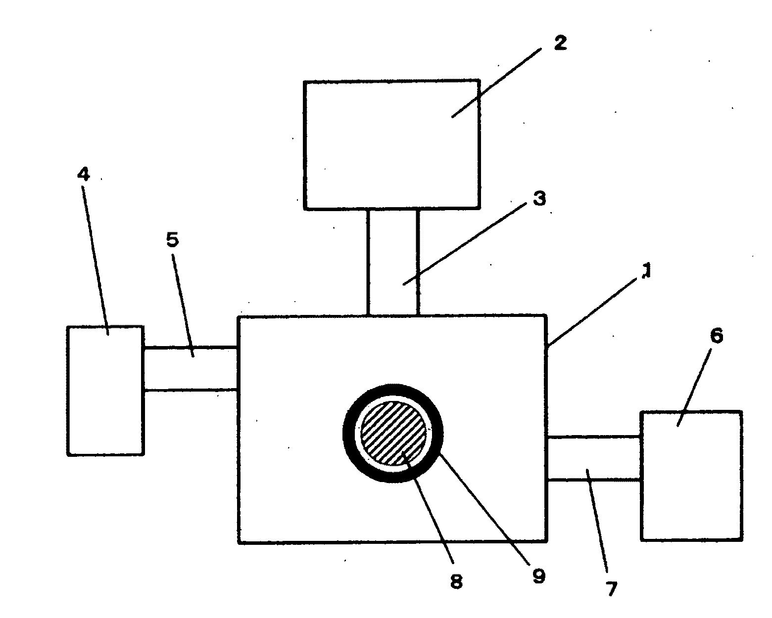
[0123]An experiment was conducted using a long tubule (made of silicone rubber) having an inner diameter of 2 mm and a length of 50 cm in the plasma generating device in FIG. 1.

[0124]The long tubule was bent to a circular form and placed around the cylindrical permanent magnet (made of neodymium, having a diameter of 3 cm, a height of 1.5 cm, and a surface magnetic field of 4000 G), which was fixed to a Teflon (registered trademark) plate.

[0125]The long tubule and the permanent magnet were both placed in the container 1. The air within the container was replaced with an oxygen gas and the pressure within the container adjusted to 0.1 Pa, and then microwaves of 4.5 GHz were emitted into the container 1.

[0126]FIG. 8 is a photograph showing how glow discharge was generated only inside the long tubule. It could be confirmed that plasma was generated throughout most of the long tubule. It is clear from this that plasma is easy to generate within a long tubule through electrodeless discha...


PUM

PropertyMeasurementUnit
pressureaaaaaaaaaa
pressureaaaaaaaaaa
temperatureaaaaaaaaaa

Abstract

An object of the invention is to provide a plasma generating device and method for generating plasma through electrodeless discharge within a long tubule and carrying out a plasma process on the inside of the long tubule. The plasma generating device has a container 1 for containing a long tubule 9, the internal pressure of which can be adjusted, a magnetic field applying means 8 for applying a magnetic field in at least part of the long tubule, and a microwave supplying means 2 for emitting microwaves into the container, and is characterized in that plasma is generated within the long tubule by emitting microwaves into the container in such a state that a magnetic field is applied in at least part of the long tubule.

Description

TECHNICAL FIELD[0001]This invention relates to a plasma generating device and method, and in particular, to a plasma generating device and method which makes it possible to generate plasma in a long tubule to be sterilized or a long tubule of which the inner wall is to be coated with a film or etched using plasma.BACKGROUND ART[0002]In recent years, various plasma processes, such as sterilizing processes, coating with a film and etching, have been used.[0003]Some conventional methods for sterilizing a long tubule, such as a catheter or an endoscope use ultraviolet rays or high pressure steam, for example. However, such methods are inefficient in sterilization and, in some cases, the material may change in quality due to the ultraviolet rays or heat. Meanwhile, methods using an ethylene oxide gas or a liquid or gas of hydrogen peroxide are highly effective, but ethylene oxide and hydrogen peroxide are toxic, and hydrogen peroxide is particularly unsafe for those who handle it and dis...

Claims


Application Information

Patent Timeline
Patent Type & Authority Applications(United States)
IPC IPC(8): C23F1/00C23F1/08C23C16/00C23C16/511B01J19/12A61L2/14
CPCH05H1/46A61L2/14
Inventor YONESU, AKIRAHAYASHI, NOBUYA
Owner YONESU AKIRA
Why Eureka
Try Eureka