Voltage controlled oscillator and electronic component

a voltage control and electronic component technology, applied in oscillator generators, angle modulation by variable impedence, electrical apparatus, etc., can solve the problems of difficult to reduce power consumption, difficult to obtain good phase noise characteristics, and large phase noise, and achieve low phase noise characteristics and high q values.

Inactive Publication Date: 2011-04-07
NIHON DEMPA KOGYO CO LTD
View PDF11 Cites 6 Cited by
  • Summary
  • Abstract
  • Description
  • Claims
  • Application Information

AI Technical Summary

Benefits of technology

[0011]The present invention has been made based on such circumstances, and an object thereof is to provide a voltage controlled oscillator having small size and capable of obtaining a good phase noise characteristic over a wide frequency band. Further, an another object of the present invention is to provide an electronic component including an inductance element and a capacitance element and capable of obtaining a high Q value as a resonance part.
[0018]According to the present invention, an inductance element formed of a conductive line is formed on a quartz-crystal substrate whose dielectric loss tangent (tan δ=1 / Q) is small to be about 0.00008, and a resonance part is configured by the inductance element and a capacitance element, so that a high Q value can be achieved. Further, a fine pattern of metal film can be formed on the quartz-crystal substrate by photolithography, so that it is possible to form a small-sized resonance part. Therefore, by forming an electronic component, which is, for instance, a voltage controlled oscillator, by using the resonance part, it is possible to realize the downsizing and to obtain a low phase noise characteristic in a wide frequency band, which is proved also by later-described data.

Problems solved by technology

Incidentally, if the VCO is used in a high frequency band of, for example, several GHz or several tens of GHz by increasing an oscillation frequency thereof, problems as follows occur.
For this reason, a good phase noise characteristic cannot be obtained, and it is difficult to reduce power consumption.
However, in the case of a), a phase noise becomes large since a multiplication circuit is used.
Further, in the case of b), a phase noise in the vicinity of an oscillation frequency of the VCO is deteriorated, and in the case of c), it becomes difficult to realize the downsizing.
Further, according to Patent Document 2, there is known a technique for making a quartz crystal being a piezoelectric substrate generate an elastic wave to use the quartz crystal as a resonator whose oscillation frequency is in about several MHz band, for example, but, it is not possible to solve the above-described problems.

Method used


Image

  • Voltage controlled oscillator and electronic component
  • Voltage controlled oscillator and electronic component
  • Voltage controlled oscillator and electronic component

Examples


Embodiment Construction

)

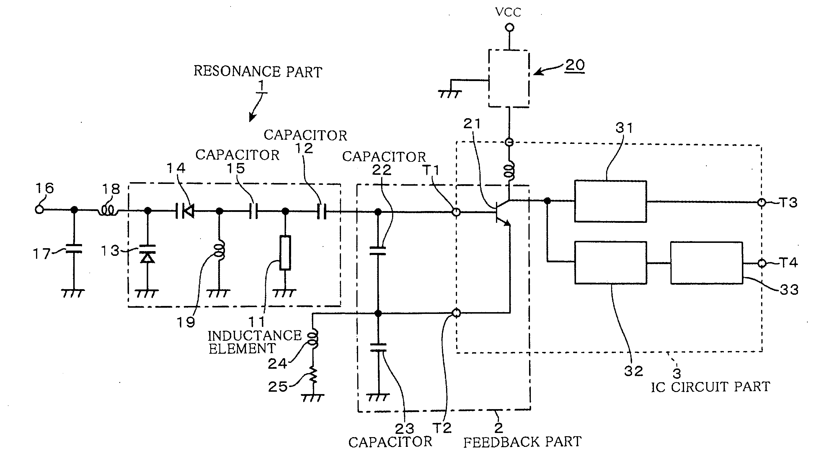
[0038]Before describing a structure of an embodiment of a voltage controlled oscillator (VCO) of the present invention, a circuitry of the embodiment will be described with reference to FIG. 1. In FIG. 1, a resonance part 1 is provided with a series circuit for series resonance including an inductance element 11 formed of a conductive line 48 as will be described later and a capacitor 12 being a capacitance element. A series circuit formed of a first varicap diode 13, a second varicap diode 14 and a capacitor 15 being a capacitance element is connected in parallel with the inductance element 11, which forms a parallel circuit for parallel resonance.

[0039]Specifically, the resonance part 1 has a series resonance frequency (resonance point) of the series circuit and a parallel resonance frequency (antiresonance point) of the parallel circuit, and an oscillation frequency is determined by a frequency of the resonance point. In this example, a constant of each circuit element is set so...


PUM


Abstract

To provide a voltage controlled oscillator having small size and capable of obtaining a low phase noise characteristic over a large span of adjustable range of frequency. A quartz crystal having a characteristic (dielectric loss tangent: tan δ) better than that of fluorocarbon resin, LTCC or the like conventionally used as a substrate of a resonance part 1, and on which a fine pattern of metal film can be formed through a photolithography method, is used as a quartz-crystal substrate 10, and a conductive line is formed on the quartz-crystal substrate 10 to form an inductance element 11 in the resonance part 1. Accordingly, since the resonance part 1 having a high Q value can be formed, it is possible to obtain a voltage controlled oscillator having small size and low loss over a wide frequency band.

Description

BACKGROUND OF THE INVENTION[0001]1. Field of the Invention[0002]The present invention relates to a technique for forming a resonance part using an inductance element and a variable capacitance element, and a voltage controlled oscillator (VCO) and an electronic component using the resonance part.[0003]2. Description of the Related Art[0004]As shown in FIG. 19, for instance, a voltage controlled oscillator (VCO) includes a resonance part having a varicap diode VD whose electrostatic capacitance varies in accordance with a control voltage and an inductance element 11, and a feedback part 2 formed of a transistor 21 being an amplifying part and two capacitors C1, C2. In this example, a frequency signal resonated in the resonance part is amplified by the transistor 21, and is fed back to a series resonant circuit via the feedback part 2, thereby forming an oscillation loop. Note that 31 in FIG. 19 denotes a buffer amplifier that amplifies the frequency signal and outputs it to the outsi...

Claims


Application Information

Patent Timeline
Patent Type & Authority Applications(United States)
IPC IPC(8): H03B5/18
CPCH03B2200/0008H03B5/1243H03B5/1203
Inventor YAMAKAWA, JUNICHIROAKAIKE, KAZUOONZUKA, TATSUNORITSUDA, TOSHIMASATAKANO, MIKIOYAMAMOTO, YASUSHIYOSHIMOTO, SUSUMU
Owner NIHON DEMPA KOGYO CO LTD
Why Eureka
Try Eureka