Waste treatment system

a technology of waste treatment and waste cake, which is applied in the direction of filtration separation, separation processes, chemistry apparatuses and processes, etc., can solve the problems of difficult to effectively eliminate the moisture content of sludge beyond a certain level, and the sludge cake retains a substantial portion of moisture, and conventional techniques are only capable of eliminating that level of moistur

Inactive Publication Date: 2011-04-14
HYDROPRESS HLDG
View PDF88 Cites 18 Cited by
  • Summary
  • Abstract
  • Description
  • Claims
  • Application Information

AI Technical Summary

Problems solved by technology

However, this sludge cake retains a substantial portion of moisture, requiring further treatment.
However, because of the consistency of the sludge cake, or due to the presence of certain polymers or flocculants within the sludge itself, it can be qu

Method used


Image

  • Waste treatment system
  • Waste treatment system

Examples


example one

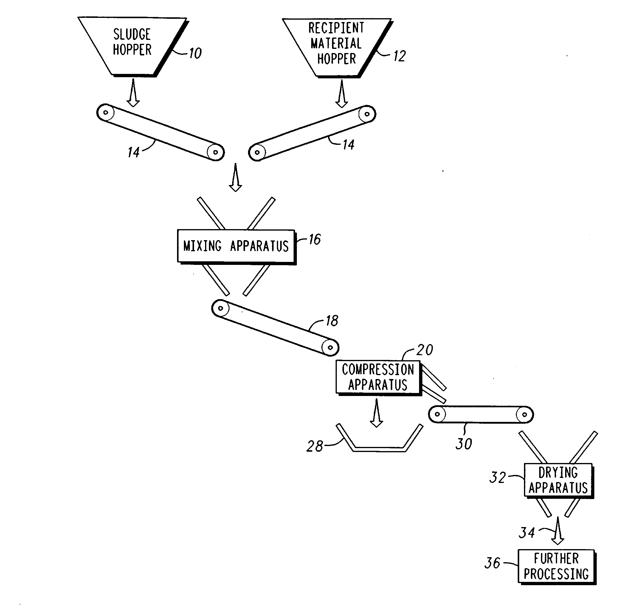
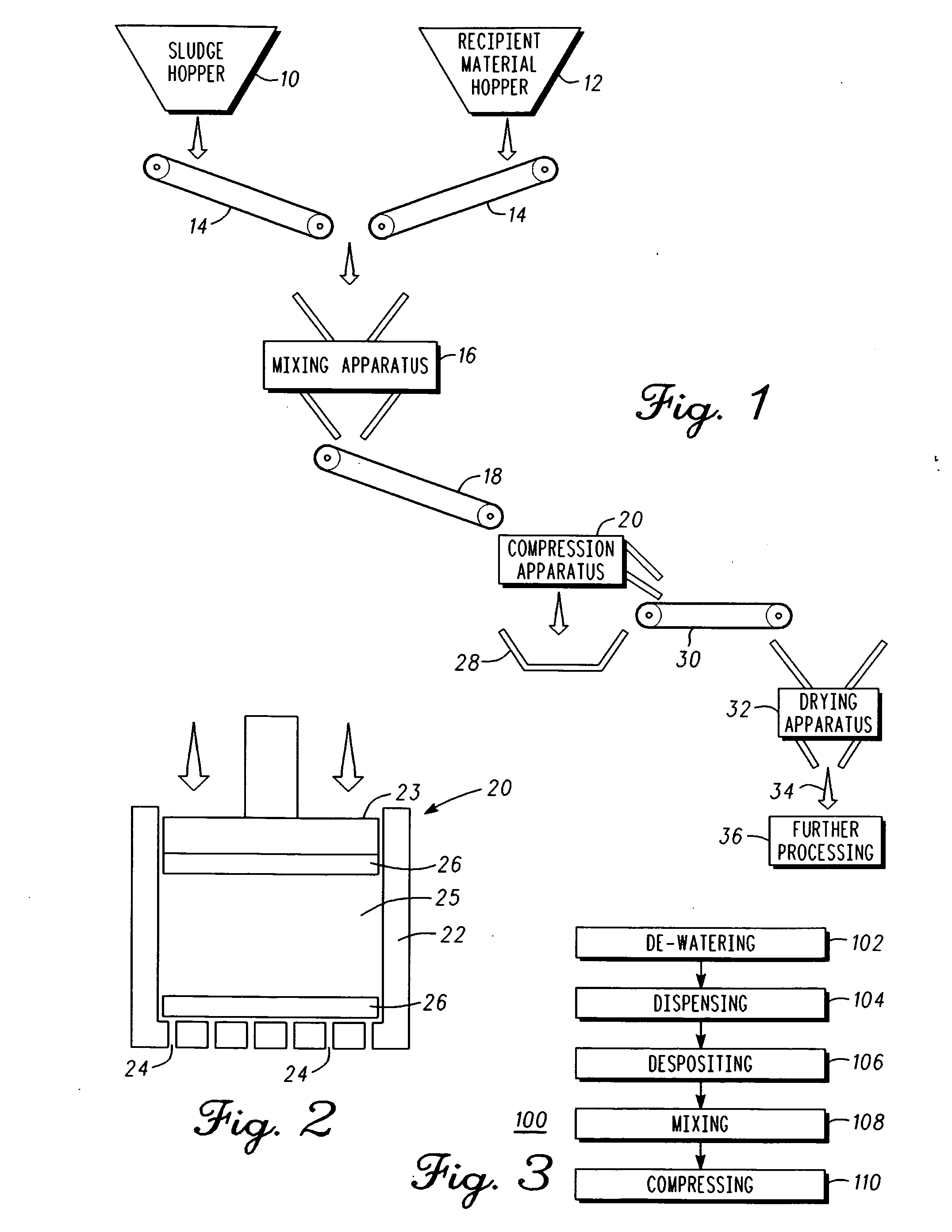
[0075]The following table shows the weight reduction produced in a small bench scale experiment for a number of different mixtures. A chamber which was twelve inches deep and had a six inch diameter was filled with 4, 6 and 8 inches of sludge and the indicated mixture. The chamber had a series of holes on the floor spaced about one centimeter apart in a series of decreasing circular arrangements. The about 40 holes had about a five millimeter diameter. A filter was placed adjacent to the floor and comprised a conventional porous belt. A like sized circular piston with a substantially flat and circular end was used to apply a downward pressure toward the floor of the chamber for about 30 to 60 seconds. The initial pressure was about 200 psi and final pressure was about 1000 psi. It was observed that most of the water escaped through the holes upon the initial downward pressure, and thereafter additional water exited the chamber. In more detail, a large amount of wastewater was expell...

example two

[0076]In a preferred embodiment, good results were achieved in the following manner. A sewage sludge sample of undigested sludge cake with a moisture level of 87% was mixed at a rate of 18% with a dry MDF wood dust. The mix was placed in the dewatering device at a depth of 5 inches (125 mm). The following results were obtained from three batches of the above mix.

[0077]Batch 1 was compressed at a pressure of 250 pounds per square inch (psi). The additive was separated from the compressed sludgecake afterwards. The moisture content of the compressed sludgecake was 44.6% moisture. This was a decrease of about 42.4 points of moisture.

[0078]Batch 2 was compressed at a pressure of 500 psi. The additive was separated from the compressed sludgecake afterwards. The moisture content of the compressed sludgecake was 36.03% moisture. This was a decrease of about 50.97 points of moisture.

[0079]Batch 3 was compressed at a pressure of 1000 psi. The additive was separated from the compressed sludge...


PUM

PropertyMeasurementUnit
Weight ratioaaaaaaaaaa
Sizeaaaaaaaaaa
Compressibilityaaaaaaaaaa

Abstract

A system and method for removing water from sludge is disclosed. The method (100) includes: de-watering (102) the sludge comprising an output from a wastewater treatment system to form a semi-solid sludge cake; dispensing (104) the semi-solid sludge cake in a hopper and dispensing a dewatering agent in a recipient dewatering agent hopper; depositing (10) the semi-solid sludge cake and the dewatering agent in a mixing device; mixing (108) the semi-solid sludge cake and the dewatering agent having a porous structure in a weight ratio of the semi-solid sludge cake to the dewatering agent of about from 1:1 to about 10:1; and compressing (110) the semi-solid sludge cake and the dewatering agent to release moisture. The system (100) provides an improved method of de-watering sludge, for more efficient processing, transporting and recycling, depending on the application.

Description

FIELD OF THE INVENTION[0001]The present invention relates to an improved system for treating waste, and in particular a sludge or a bio-solid material from a wastewater treatment plant, for example, human, animal, chemical, pharmaceutical, semiconductor, food, aluminium, ferric processing and the like, waste.BACKGROUND OF THE INVENTION[0002]In practically all municipal wastewater treatment plants, waste water is separated into treated water and waste material. The waste material is in the form of a sludge comprising both solid and liquid material, the majority of the material being liquid. Before transporting the waste material from one location to another for further processing, it is advantageous to remove as much moisture or liquid from the sludge as possible, as this reduces the weight of the sludge. Also, the lower the percentage of moisture or liquid in the sludge, the lesser the chance of groundwater contamination due to seepage from the sludge.[0003]It is known to initially ...

Claims


Application Information

Patent Timeline
IPC IPC(8): C02F11/12C02F11/14C02F11/122C02F11/123C02F11/125C02F11/13C02F11/147
CPCC02F11/122C02F11/14C02F11/125C02F11/123C02F11/147C02F11/13
Inventor O' REILLY, DOMINICK
Owner HYDROPRESS HLDG
Why Eureka
Try Eureka