Feeding System for Semi-Solid Metal Injection

a semi-solid metal injection and feeding system technology, applied in the field of die casting moulds, can solve the problems of significant differences between the rheological properties of semi-solid metal alloys and the molten metals used in conventional die casting, limited understanding of the semi-solid process, and casting defects

Inactive Publication Date: 2011-05-12
NAT RES COUNCIL OF CANADA
View PDF5 Cites 30 Cited by
  • Summary
  • Abstract
  • Description
  • Claims
  • Application Information

AI Technical Summary

Benefits of technology

Applicant has discovered, unexpectedly, that placement of the outlet on the wall of the piston chamber does not appreciably detract from the flow characteristics of the ejector, as would be

Problems solved by technology

This technique is relatively new and there is a limited understanding of the semi-solid process.
While mould geometry and feed system designs were generally adapted from conventional die-casting nozzles, there are significant differences between the rheological properties of semi-solid metal alloys and the molten metals used in conventional die casting.
This design avoids an external chamber intermediate the injector cavity and the mould cavity, at the expense of limiting a shape of the moulds that can be injected (as they need to include space at the opening to hold the tip of the injector), and result in the imprinting of this tip on the surface of the moulded part, as well as irregular ears produced between the tip and the mould, that would typically have to be removed by post cast machining.
Casting defects are a problem with high end applications of this method, generally in the form of inclusions (such as oxides or lubricants), porosities, surface blisters, etc.
Some defects are related to outside layer drag, which is caused by a skin formed on the semi-solid metal alloy billet while it is dispensed into the injector, while it dwells in the injector and as the injector is actuated.
It is very difficult to avoid these problems as the material cools very rapidly on contact with the chamber.
The skin has an important impact on the flow properties of the semi-solid metal alloy billet potenti

Method used


Image

  • Feeding System for Semi-Solid Metal Injection
  • Feeding System for Semi-Solid Metal Injection
  • Feeding System for Semi-Solid Metal Injection

Examples


example 1

Simulations

A series of simulations were performed to examine design options for semi-solid injection. The objective of the simulations was to produce a design that retains the greatest flow laminarity, while trapping the greatest majority of inclusions. To this end, numerous simulations were performed with different flow parameters typical of semi-solid injection. The specific dimensions of the injection feed system chosen for analysis are shown in FIG. 3b. The principle simulation parameters were:

Mould temperature300°C.Material (chamber) temperature585°C.Injection Speed (Piston)0.3m / sBillet dimensions80 mm diameter by 180 mm longMass of billet2.1-2.3kgMaterial compositionAL 357

The relevant rheological properties of AL 357 are well known in the art. The software Procast 2006 from ESI GROUP was use for all simulations. Specifically, these simulations were done by using isotherm flow solver module of the Procast software.

As a result of these simulations, a model having improved trappi...

example 2

Prototype Infection Feed System

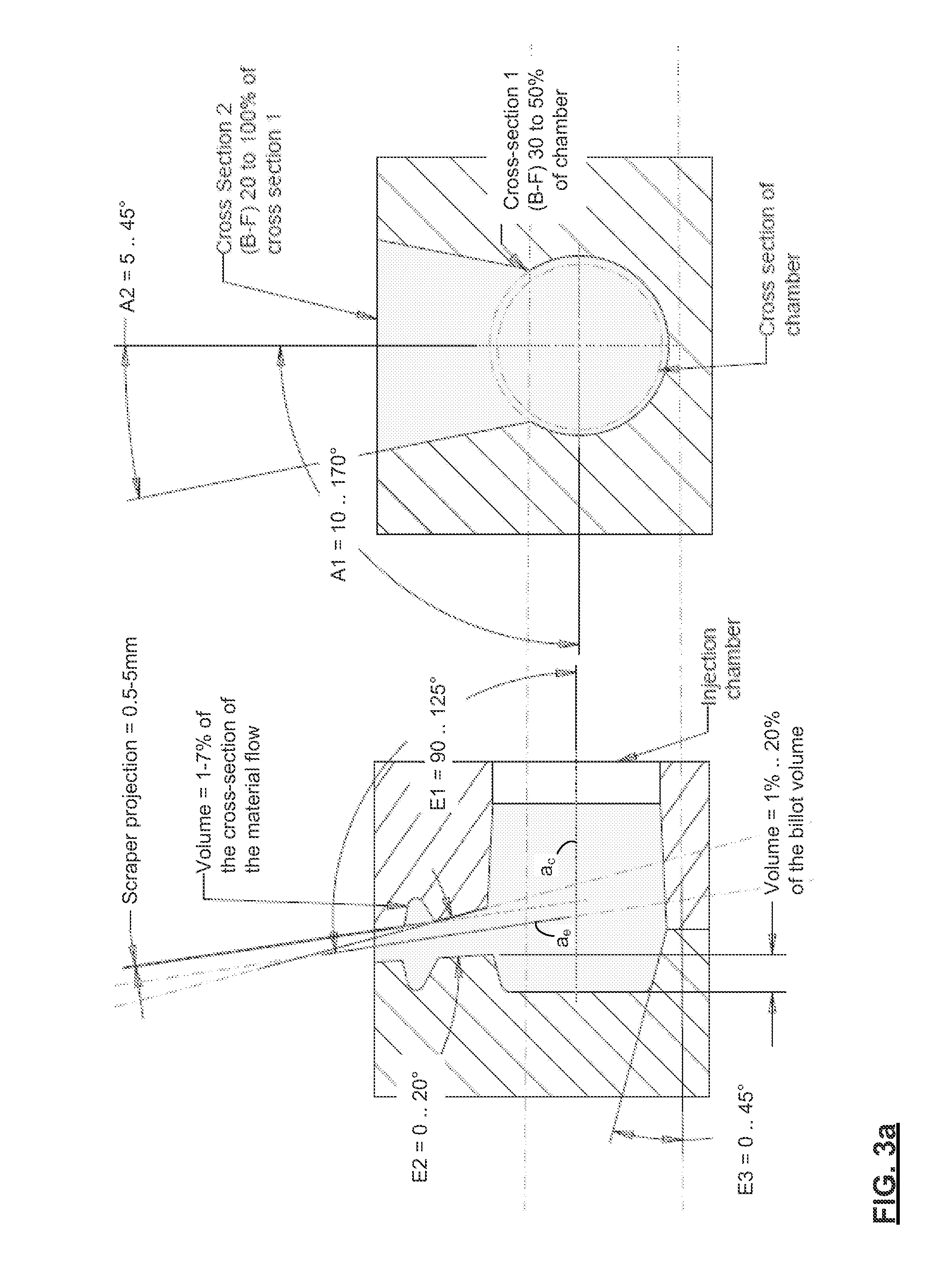
A horizontal injection feed system was produced having the specifications shown in FIG. 3a. This injection feed system is shown in FIG. 5. The injection feed system was formed as a H13 steel insert for an existing cavity and piston set made by Buhler (530 ton). The insert was formed of 6 pieces: four retention blocks, and two mating pieces that form the upper and lower parts of the end of the chamber.

Characterization

FIGS. 6a,b are images of solidified parts from the feed system of FIG. 1. Metallographic analysis performed on a section of one of them (FIG. 6a) using an optical microscope shows the flow of inclusions up a slope caused by a ramp of skin in the annular skimming trough, and the advance of these inclusions into the concentric neck of the chamber. FIG. 6b is an X-ray image showing the inclusions within the neck, as well as the head and around the right angle bend.

A study of this horizontal injection feed system produced 200 parts. Several doz...


PUM

PropertyMeasurementUnit
Lengthaaaaaaaaaa
Lengthaaaaaaaaaa
Fractionaaaaaaaaaa

Abstract

A semi-solid metal alloy injection feed system for reduced inclusion injection moulding comprises a substantially closed injection chamber for containing a billet of semi-solid metal alloy, and thrusting the billet through the injection chamber into a mould, wherein the injection chamber has a first section defined by a wall with an inner contour for mating with a bearing surface for reciprocating motion of the bearing surface within the first section, along a center axis of the injection chamber; and the injection chamber has an outlet in fluid communication with the mould, the outlet provided at an opening in the injection chamber that is offset with respect to the center axis, and is disposed at an angle of 90° to 125° from the center axis. There is no neck or throttling between the chamber and the outlet. A butt end trap is preferably formed that requires inclusions that are principally on a bottom side of the injector to travel a relatively long ways to enter the outlet.

Description

FIELD OF THE INVENTIONThe present invention relates in general to die casting moulds, and, in particular, to a mould for die casting semi-solid metal and like materials that require lubricated injection, that decreases lubricant contamination and waste, and simplifies demoulding by placing the exit port to the mould directly on a piston chamber at a decentralized position that is oriented substantially opposite where lubricant pools.BACKGROUND OF THE INVENTIONPressure injection of semi-solid metal alloy (a finely divided solid metal phase blended in a molten metal phase) into a mould is of growing importance because of the strength and reproducibility of parts that can be achieved. In the semi-solid state material can be forced through small apertures at high rates, as a relatively low shear resistance is exhibited. As a result the technique yields near net shape production of complex, detailed shapes (even with thin walls) and advantageously provides high part consistency, and high...

Claims


Application Information

Patent Timeline
IPC IPC(8): B22D17/00
CPCB22D17/2023B22D17/007
Inventor ZHENG, CHANG-QINGLAPLUME, FLORENTIN
Owner NAT RES COUNCIL OF CANADA
Why Eureka
Try Eureka