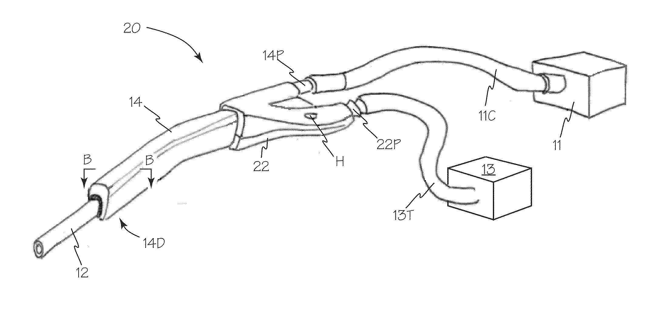
[0007]The illuminated suction apparatus includes suction and illumination functions integrated into a hand-held device suited to meet the ergonomic needs of the physician. The hand-held, repositionable suction function already prevalently used in
surgical procedures is surrounded by an illuminated
waveguide which enables the physician to apply lighting directly to the desired region of the
anatomy below the
skin regardless of incision angle, depth, and surrounding anatomical obstructions. The illumination
waveguide is a
solid structure designed to specifically guide light from a high-intensity
light source and is fabricated using an optical-grade
polymer with a specific index of
refraction such as cyclo-olefin
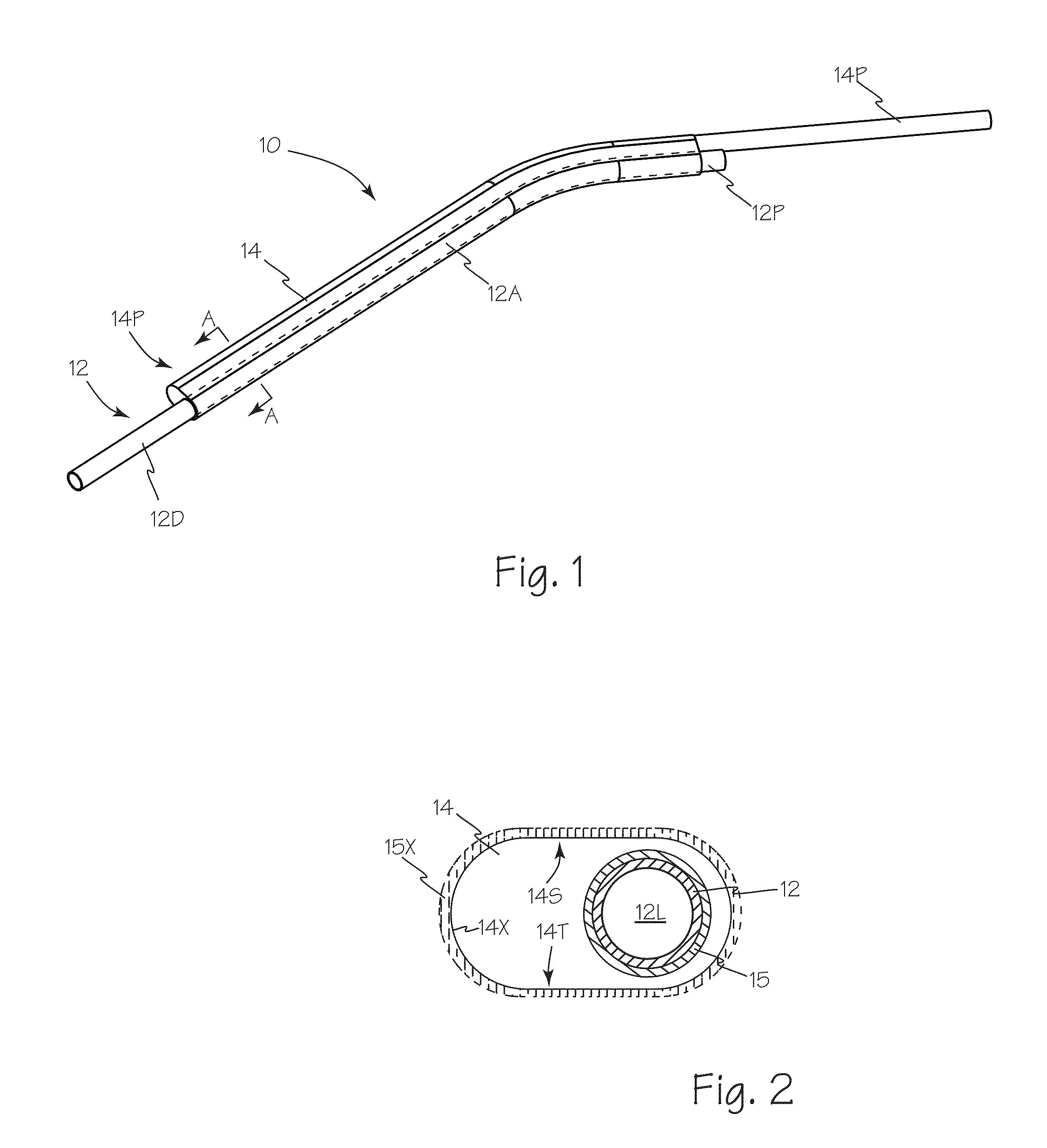
polymer or
copolymer or any other suitable acrylic or plastic. Furthermore, the illumination waveguide can be engineered to efficiently transmit light from its distal output by sheathing or surrounding it with a second material of lower index of
refraction properly coordinated to the index of
refraction of the core material to preserve
Total Internal Reflection (TIR). This
solid-state, structure guided illumination waveguide is powered via a fiber optic cable connected to a
high intensity light source such as 300W
xenon sources supplied by Luxtec, BFW, and others.
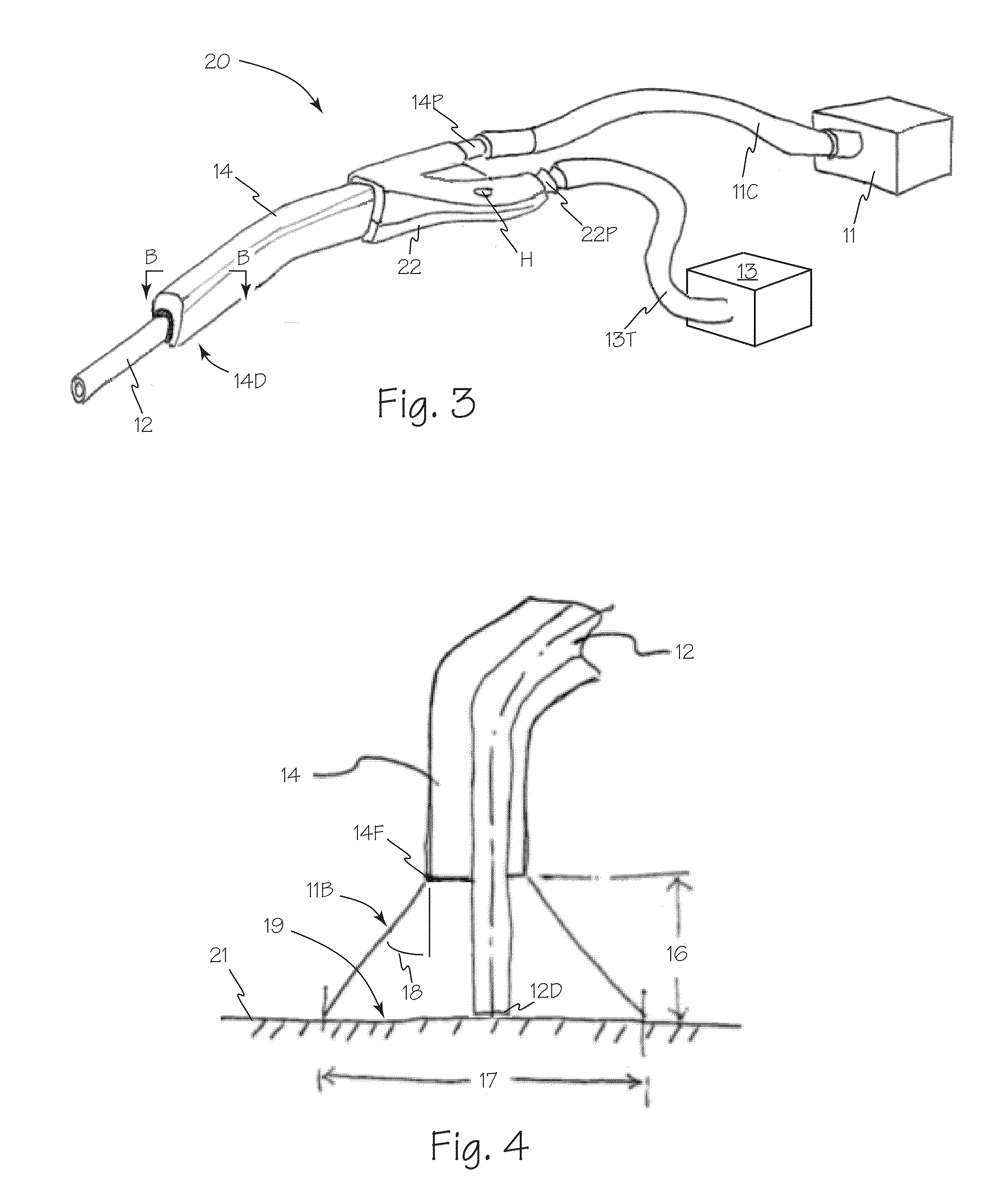
[0009]The use of a generally
solid waveguide for suction illumination, rather than optical fibers, eliminates losses due to the non-transmissive spaces between the optical fibers and reduces losses solely to those associated with Fresnel reflections. The marked reduction in losses associated with a fiber / fiber junction allows for
high intensity light transmission to the waveguide without significant heating of the interface or need for
heat sink devices or mechanisms at the interface. With a fiber to waveguide connection, light from a standard 300
watt light source can be transmitted with use of standard connectors such as ACMI, with a
steady state temperature below the temperatures harmful to
body tissue without design alteration.
[0010]Use of
total internal reflection and light mixing in an illumination waveguide enables control of the output light profile and enables custom illumination profiles. Microstructures can be applied to any suitable surfaces of the illumination waveguide and light can be extracted incrementally along the walls of the device with injection molded structures and other suitable structures at minimal added cost. Use of sequential extraction surfaces, changes in the
numerical aperture of the device as a function of position, use of extraction structures—either micro or
macro structural, with or without changes in the
numerical aperture, selective cladding, selective reflective coatings, etc, all can be used to shape the output profile of the waveguide to meet the design specifications or light specifications requested by the user for specific surgical suction illumination applications.
[0011]The device is meant to be disposable, fabricated out of low cost materials to enable leverage of manufacturing efficiencies through use of processes such as high-volume injection molding, over-molding, and
metal &
polymer extrusion. Device
assembly would be engineered to minimize labor costs. A low cost, high-performance combination device provides an attractive alternative to existing discrete illumination and suction devices while minimizing incremental cost to the user.
[0014]In an alternate configuration, the distal tip of the suction tube may be configured to transmit light or reflect light such that the surgeon sees the distal tip of the suction as illuminated such that he / she can localize the distal tip of the suction device in their
peripheral vision without directly looking at or focusing on the tip of the device. Extending a
thin layer of the waveguide to the tip can provide the effect. Strategies that implement this effect include but are not limited to: (a) waveguide extended to the tip with or without surface extraction features to cause light to back reflect or scatter off the tip, (b) Use of a
thin layer of optically transmissive material with high
scattering coefficient to cause the suction device to glow (c)
reflective surfaces applied to the outside of the central suction device (d)
reflective surfaces applied with imperfections on the surface to reflect or scatter the light off the outer surface (e) use of a cladding material applied to the walls of the inner suction tube that transmits or scatters a portion of the output light, the input to the cladding being either an imperfection in the cladding or naturally occurring leakage, (f) fluorescent
coating on the tip, (g) phosphorescent coatings (h) use of embedded or graded reflectors along or at the tip of the device. Alternatively, the distal tip geometry could be formed to intentionally scatter light (square edges, etc).
[0015]One or more surfaces in an optical waveguide sheath or adapters or connectors may be polarized using any suitable technique such as micro-optic structure, thin
film coating or other. Use of polarized light in a surgical environment may provide superior illumination and coupled with the use of complementary polarized coatings on viewing devices such as cameras or surgeon's glasses may reduce reflected glare providing less
visual distortion and more accurate color rendering of the
surgical site. One or more surfaces of an optical waveguide sheath may also include light filtering elements to emit light of one or more frequencies that may enhance
visualization of specific tissues.

