Process for Obtaining a Catalyst Composite

a composite and catalyst technology, applied in the field of catalyst composites, can solve the problems of limited supply and increasing crude oil supply, insufficient physical mixing of zeolite with rare earth compound, and little effect on catalytic performance, and achieve high propylene yield and high propylene/ethylene ratio. , the effect of high stability

Active Publication Date: 2011-05-19
TOTAL RES & TECH FELUY
View PDF7 Cites 19 Cited by
  • Summary
  • Abstract
  • Description
  • Claims
  • Application Information

AI Technical Summary

Benefits of technology

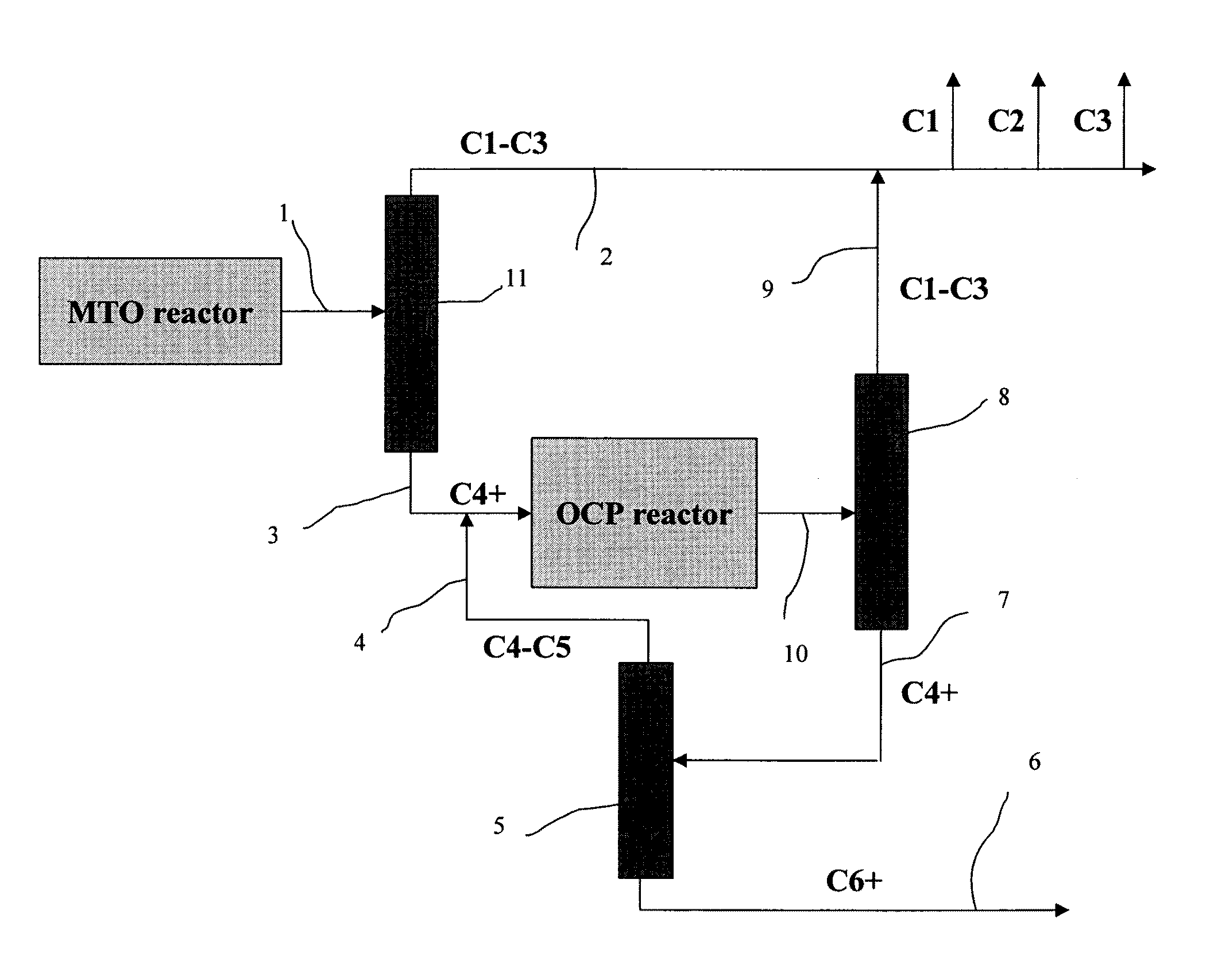
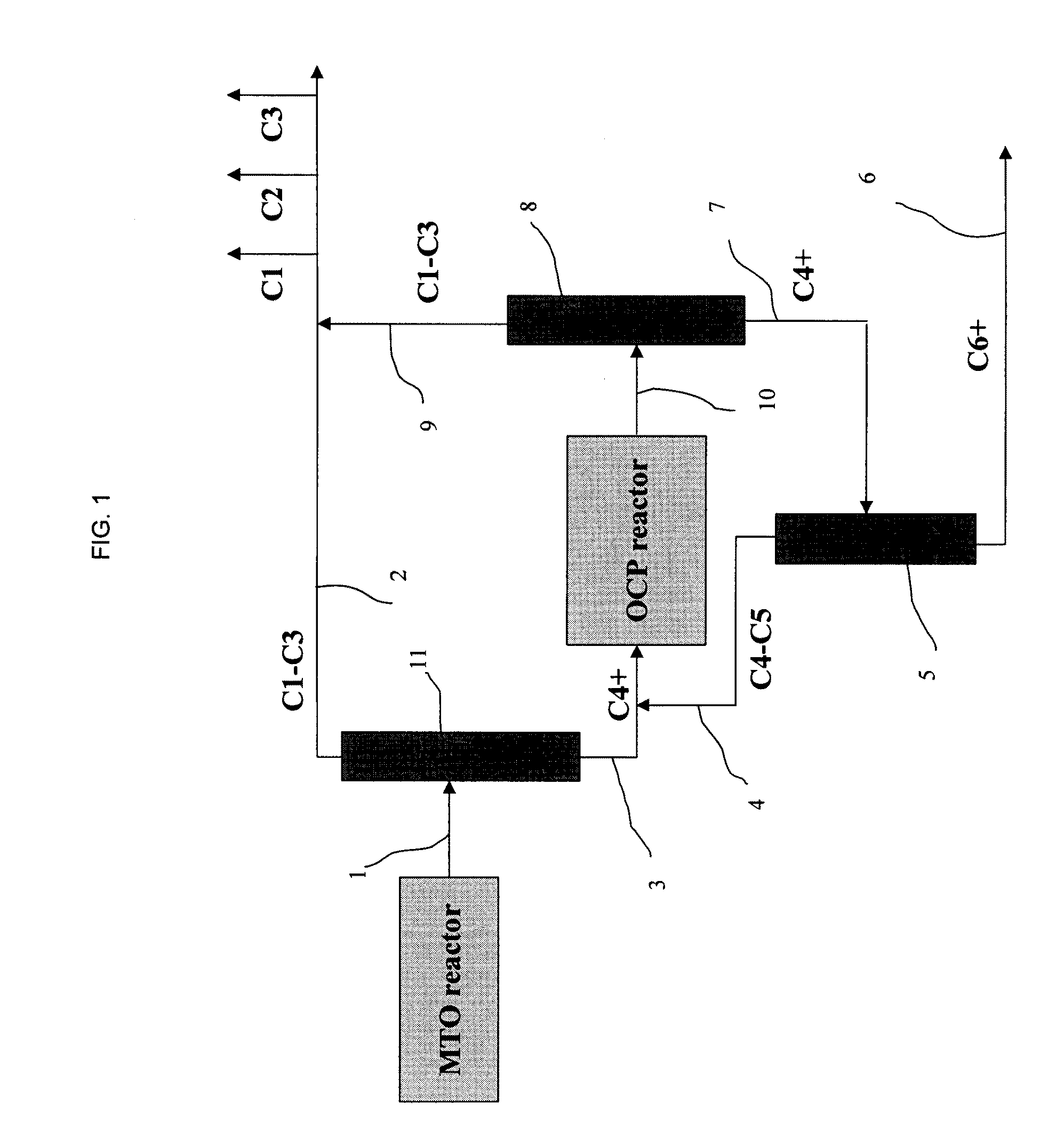
[0052]The catalyst composites according to the invention show high propylene yield, high propylene / ethylene ratio, high stability, high propylene purity and reduced selectivity to paraffin's and to aromatics in the XTO process. These catalysts also provide the additional flexibility for ethylene and C4+ recycling to increase propylene production. The average propylene yield can be substantially enhanced by using the catalyst composite of the invention in a combination of XTO and OCP process.

Problems solved by technology

The limited supply and increasing cost of crude oil has prompted the search for alternative processes for producing hydrocarbon products.
It is stated that mere physical mixing of the zeolite with the rare earth compound is not sufficient.
There is also no indication that this catalyst can be used in XTO processes.
Usually, they have very little effect on catalytic performance.
Typically, rare earth elements, which are very expensive, are used in such catalyst composites.
However, ion-exchange / impregnation potentially leads to the modification of the acidity of catalytic sites throughout the whole microporous structure of the molecular sieve.
This could lead to decreased catalytic activity.
Without taking special precautions during pre-treatment and catalyst formulation these compounds may partially damage the molecular sieve pore structure.

Method used


Image

  • Process for Obtaining a Catalyst Composite
  • Process for Obtaining a Catalyst Composite

Examples


example 1

[0134]A sample of zeolite ZSM-5 with Si / Al=12 (CBV2314) from Zeolyst International was first calcined for 6 hours at 550° C. (60° / min heating rate). It was then was steamed at 680° C. for 2 hours in 100% steam. The steamed solid was treated with a 3.14-M solution of H3PO4 for 18 h under reflux conditions (4,2liter / 1 kg of zeolite). The solid was then separated by filtration from the solution. The obtained solid was dried first at 110° C. for 16 h and then at 400° C. for 3 h.

example 2

[0135]The sample obtained from example 1 was blended with 10 wt % of xonotlite (Ca6Si6O17(OH)2) and subjected under reflux conditions in contact with hot water for 2 hours. Then the solid was separated by filtering from the solution, dried immediately at 110° C. for 16 hours and steamed at 600° C. for 2 hours in 100% steam (Atomic ratio Si / Al 15, P-content 2.5 wt %). The sample is hereinafter identified as SAMPLE A.

example 3

[0136]The sample described in example 1 was subjected to reflux conditions for 2 hours in contact with hot water under. Then the solid was separated by filtering from the solution and dried immediately at 110° C. for 16 hours and steamed at 600° C. for 2 hours in 100% steam. (Atomic ratio Si / Al 15, P-content 2.0 wt %). Contrary to example 2, no calcium compound is added.

[0137]The sample is hereinafter identified as Comparative I.


PUM

PropertyMeasurementUnit
wt %aaaaaaaaaa
mole ratioaaaaaaaaaa

Abstract

A process for obtaining a catalyst composite comprising the following steps:
a). selecting a molecular sieve having pores of 10-or more-membered rings
b). contacting the molecular sieve with a metal silicate different from said molecular sieve comprising at least one alkaline earth metal and one or more of the following metals: Ga, Al, Ce, In, Cs, Sc, Sn, Li, Zn, Co, Mo, Mn, Ni, Fe, Cu, Cr, Ti and V, such that the composite comprises at least 0.1 wt % of silicate.

Description

FIELD OF THE INVENTION[0001]The present invention relates to a catalyst composite comprising a molecular sieve and a catalyst promoter as well as their use in conversion of organics to light olefins. More precisely the molecular sieves of the invention are obtained from crystalline aluminosilicates having pores of 10-or more-membered rings. The invention is useful as a catalyst in a variety of processes including cracking, hydrocracking, isomerisation, reforming, dewaxing, alkylation, transalkylation, and conversion of oxygenates (or halogenide-containing or sulphur-containing organic compounds) to light olefins.BACKGROUND OF THE INVENTION[0002]The limited supply and increasing cost of crude oil has prompted the search for alternative processes for producing hydrocarbon products. One such process is the conversion of oxygen-containing (for example methanol), halogenide-containing or sulphur-containing organic compounds to hydrocarbons, in particular, to light olefins, i.e. C2 to C4 ...

Claims


Application Information

Patent Timeline
Patent Type & Authority Applications(United States)
IPC IPC(8): C07C1/20B01J29/40B01J37/04B01J37/10B01J37/06B01J37/08B01J37/02B01J37/30B01J37/28C07C1/26C07C1/32C07C4/06
CPCB01J21/16B01J27/16B01J29/06B01J29/40B01J23/00B01J2229/42C07C1/20B01J2229/186C07C11/02Y02P30/20Y02P30/40B01J29/60B01J29/7007B01J29/7046B01J29/7038B01J29/65B01J29/08B01J29/7026B01J2029/081B01J37/10B01J37/28B01J2229/16C07C4/06C07C2529/40C08F10/06
Inventor NESTERENKO, NIKOLAIVERMEIREN, WALTERVAN DONK, SANDER
Owner TOTAL RES & TECH FELUY
Why Eureka
Try Eureka