
Method for producing glass film, method for treating glass film and glass film laminate

a technology of glass film and laminate, which is applied in the direction of film/foil adhesives, light beam reproducing, instruments, etc., can solve the problems of glass substrate breakage, low flexibility, weak tensile stress of glass used for a substrate, etc., and achieves more stable fixation and laminated, good contact, and easy peeling

Inactive Publication Date: 2011-05-26
NIPPON ELECTRIC GLASS CO LTD
View PDF13 Cites 34 Cited by
  • Summary
  • Abstract
  • Description
  • Claims
  • Application Information

AI Technical Summary

Benefits of technology

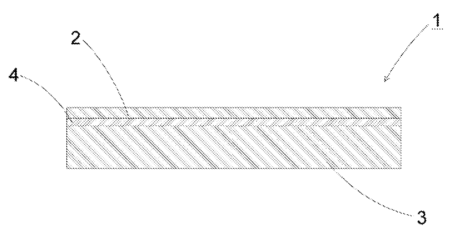
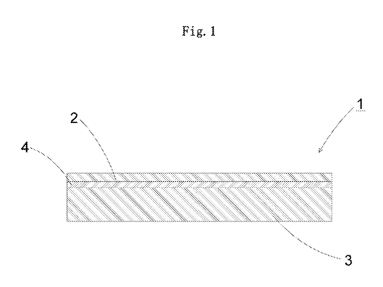
[0020]According to the present invention, the glass film laminate is formed by laminating the glass film having a surface roughness Ra of 2.0 nm or less on the surface of the inorganic thin film having a surface roughness Ra of 2.0 nm or less formed on the surface of the supporting glass in a state of being in contact with each other, resulting in good contactness between the glass film and the inorganic thin film. Thus, it is possible to fix and laminate the glass film and the supporting glass via the inorganic thin film without use of a pressure-sensitive adhesive. As a result, the glass film is not displaced with respect to the supporting glass during the device production-related treatment or the like, and hence the glass film can be positioned at a correct position. Further, the glass film does not adhere to the inorganic thin film even when the glass film is subjected to heating, and hence the glass film can be easily peeled off from the supporting glass (inorganic thin film) after the treatment. Moreover, after being peeled off, the glass film results in a clean one without adhesion of a pressure-sensitive adhesive or the like.
[0021]On the other hand, when the surface roughnesses Ra of the inorganic thin film and glass film exceed 2.0 nm, the contactness between the both glasses lowers. As a result, the glass film and the supporting glass cannot be firmly fixed and laminated without a pressure-sensitive adhesive.
[0022]When an oxide thin film is adopted as the above-mentioned inorganic thin film, the glass film and the supporting glass can be more stably fixed and laminated.
[0023]Further, by laminating the glass film and the supporting glass so that at least a part of an edge portion includes a step, in a case of the glass film protruding from the supporting glass, it is possible to peel off the glass film and the supporting glass more easily in a more secure manner. On the other hand, in a case of the supporting glass protruding from the glass film, it is possible to properly protect an end portion of the glass film from striking or the like.
[0024]The glass film laminate of the present invention formed by laminating the supporting glass and the glass film via the inorganic thin film has better handling easiness compared with a glass film as a single member. Further, even after the glass film laminate is subjected to the device production-related treatment involving heating or the like, the glass film can be easily peeled off from the supporting glass. In addition, a pressure-sensitive adhesive or the like is not used, and hence, after the glass film is peeled off, the glass film is without adhesion of the pressure-sensitive adhesive or the like and is clean.
[0025]By setting the GI value of each of the surface of the inorganic thin film and the surface of the laminate side of the glass film to 1000 pcs / m2 or less, the glass film and the supporting glass can be laminated and fixed more firmly.

Problems solved by technology

However, glass used for a substrate is weak in tensile stress unlike a resin film, and hence is low in flexibility.
Thus, application of a tensile stress on a surface of a glass substrate by bending the glass substrate leads to the breakage of the glass substrate.
However, when a glass film is used as a glass substrate for those electronic devices, the glass film breaks due to a stress change even at a small amount, because glass is a brittle material.
Thus, there is a problem in that the handling of the glass film is very difficult, when the above-mentioned various electronic device production-related treatments are carried out.
In addition, there is another problem in that a glass film having a thickness of 200 μm or less is rich in flexibility, and hence the positioning of the glass film is difficult when the treatment is carried out, and displacement or the like in patterning may occur.
In addition, problems such as displacement hardly occur when the positioning is carried out during the treatment, because the support glass has a high rigidity.

Method used


Image

  • Method for producing glass film, method for treating glass film and glass film laminate
  • Method for producing glass film, method for treating glass film and glass film laminate
  • Method for producing glass film, method for treating glass film and glass film laminate

Examples


example 1

[0066]Hereinafter, the method of producing a glass film of the present invention is described in detail based on examples, but the present invention is not limited to those examples.

[0067](Lamination Test)

[0068]A transparent glass sheet having a rectangular shape and having 250 mm in length, 250 mm in width, and 700 μm in thickness was used as a supporting glass. A glass film having 230 mm in length, 230 mm in width, and 100 μm in thickness was used as a glass film to be laminated on the supporting glass. Used for the supporting glass and the glass film was alkali-free glass manufactured by Nippon Electric Glass Co., Ltd. (Production name: OA-10G, thermal expansion coefficient at 30 to 380° C.: 38×10−7 / ° C.). The glass formed by the overflow down-draw method was used without polishing as it is, or by appropriately controlling amounts of polishing and chemical etching, to thereby control the surface roughness Ra. As shown in Table 1, ITO and Ti were each formed into an inorganic thin...


PUM

PropertyMeasurementUnit
Temperatureaaaaaaaaaa
Thicknessaaaaaaaaaa
Thicknessaaaaaaaaaa

Abstract

A method of producing a glass film comprises a first step of forming an inorganic thin film on a surface of a supporting glass so that a surface of the inorganic thin film after being formed has a surface roughness Ra of 2.0 nm or less after film formation, a second step of forming a glass film laminate by laminating a glass film having a surface roughness Ra of 2.0 nm or less on the surface of the inorganic thin film in a state of being in contact with each other, a third step of carrying out treatment involving heating with respect to the glass film laminate, and a fourth step of peeling off the glass film from the supporting glass after the treatment involving heating.

Description

TECHNICAL FIELD[0001]The present invention relates to a method of producing a glass film which is used for a flat panel display such as a liquid crystal display and an OLED display, a glass substrate for devices such as a solar cell, a lithium ion battery, a digital signage, a touch panel, and an electronic paper, a cover glass for devices such as an OLED lighting device, a package for a medicinal product, and the like, and relates to a glass film laminate which is supported with a supporting glass.BACKGROUND ART[0002]From the viewpoint of space saving, in recent years, there have been widely used flat panel displays such as a liquid crystal display, a plasma display, an OLED display, and a field emission display, in place of a CRT type display conventionally and widely used. Further reduction in thickness is demanded for those flat panel displays. In particular, it is required that the OLED display be easily carried by being folded or wound and be usable not only on a flat surface ...

Claims


Application Information

Patent Timeline
IPC IPC(8): B32B7/02B32B17/06B32B5/00B32B38/10
CPCC03C17/3411C03C2217/77H01L51/52Y10T428/26Y10T428/24942Y10T428/266B32B17/06B32B7/06H05B33/02H10K50/80B32B37/06B32B38/10B32B2457/20
Inventor TOMAMOTO, MASAHIROTAKAYA, TATSUYATAKIMOTO, HIROSHIORIGUCHI, NAGATOSHI
Owner NIPPON ELECTRIC GLASS CO LTD
Learn More