Method and system for formal safety verification of manufacturing automation systems

a technology for automation systems and safety verification, applied in the field of automation logic testing, can solve the problems of limited hardware-based verification testing, logic testing dependent on physical inputs and manual triggers may not be repeatable, and the entire state space of safety logic is not fully evaluated or verified. , to achieve the effect of improving verification confidence, reducing verification costs, and reducing development tim

Inactive Publication Date: 2011-05-26
GM GLOBAL TECH OPERATIONS LLC
View PDF0 Cites 15 Cited by
  • Summary
  • Abstract
  • Description
  • Claims
  • Application Information

AI Technical Summary

Benefits of technology

[0006]The use of formal methods for the verification of safety logic can result in reduced development time, decreased verification costs, improved verification confidence and expanded verification over the entire state space of the logic system. Provided herein is a system and method for formal verification of safety control logic in manufacturing automation systems which includes generating a formal mathematical model representing the safety logic to be verified and a formal mathematical model of the corresponding verification testing specifications, and comparing the formal or mathematical model of the safety logic against the formal or mathematical model of the testing specifications to verify and certify the behavior of the safety logic. This formal safety logic method and system of verification can be used to overcome limitations of traditional hardware-based verification systems, including expanding the verification criteria beyond the typical “fail to safe” evaluation, providing for the certification of safety modules including supplier provided (black box) modules and creating a library or database of certified logic and modules with corresponding testing specifications. The library can be used and reused to increase the efficiency and repeatability of safety logic development and verification testing and for control logic changes including reverification after modification of the automation safety system or logic. System behaviors in addition to “fail to safe” and conditions such as low probability events which are not typically verified in a physical test-bed scenario can be tested and verified using formal methods, and may include, for example, stay safe state without reset behavior, return to active state after reset transition, stay active state or false alarm negation, and response time requirements.

Problems solved by technology

Setting-up and configuring the automation and safety hardware for testing, conducting the testing and recording and reporting the verification testing results is manually intensive and can often be inconsistent because of ambiguities in the informal specifications and variation in interpretation by the test engineer.
Typically, the entire state space of the safety logic is not fully evaluated or verified, due to resource, timing and cost limitations as well as physical constraints of the hardware-based testing which prevent evaluation of the entire state space conditions, transitions and behaviors.
Logic testing dependent upon physical inputs and manual triggers may not be repeatable and may be limited in ability to test timing response, simultaneous events, negative specification conditions and low probability combinations.
Hardware-based verification testing may also be limited based on the availability of physical hardware, and may be further constrained if the hardware is prototype equipment or if simulated inputs are used where no equipment is available.
Repeat testing may be required at production deployment, to verify changes and revisions, which may cause increased costs and potential delay in production implementation if safety logic corrective actions and further reverification is required.

Method used


Image

  • Method and system for formal safety verification of manufacturing automation systems
  • Method and system for formal safety verification of manufacturing automation systems
  • Method and system for formal safety verification of manufacturing automation systems

Examples


Embodiment Construction

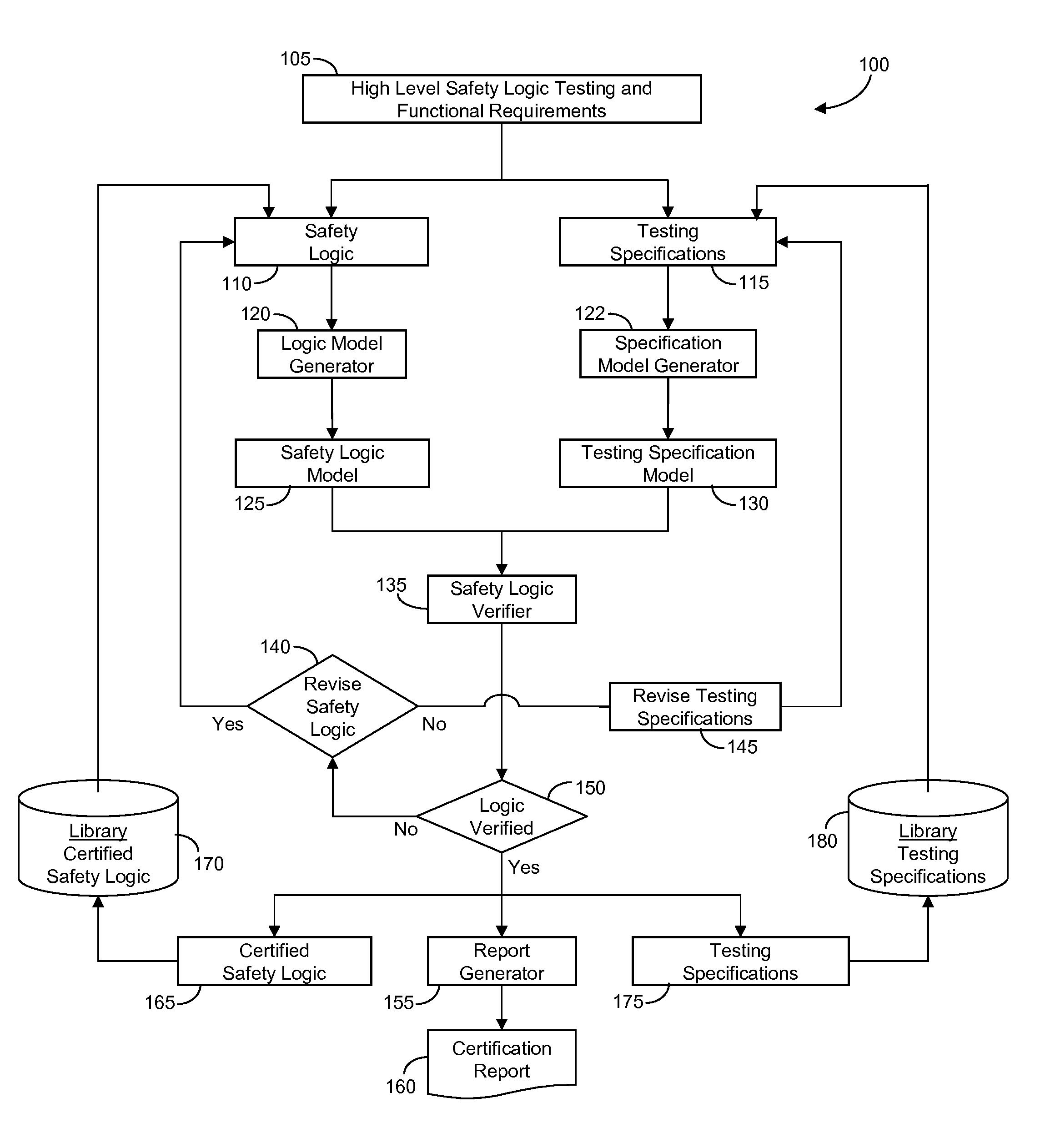
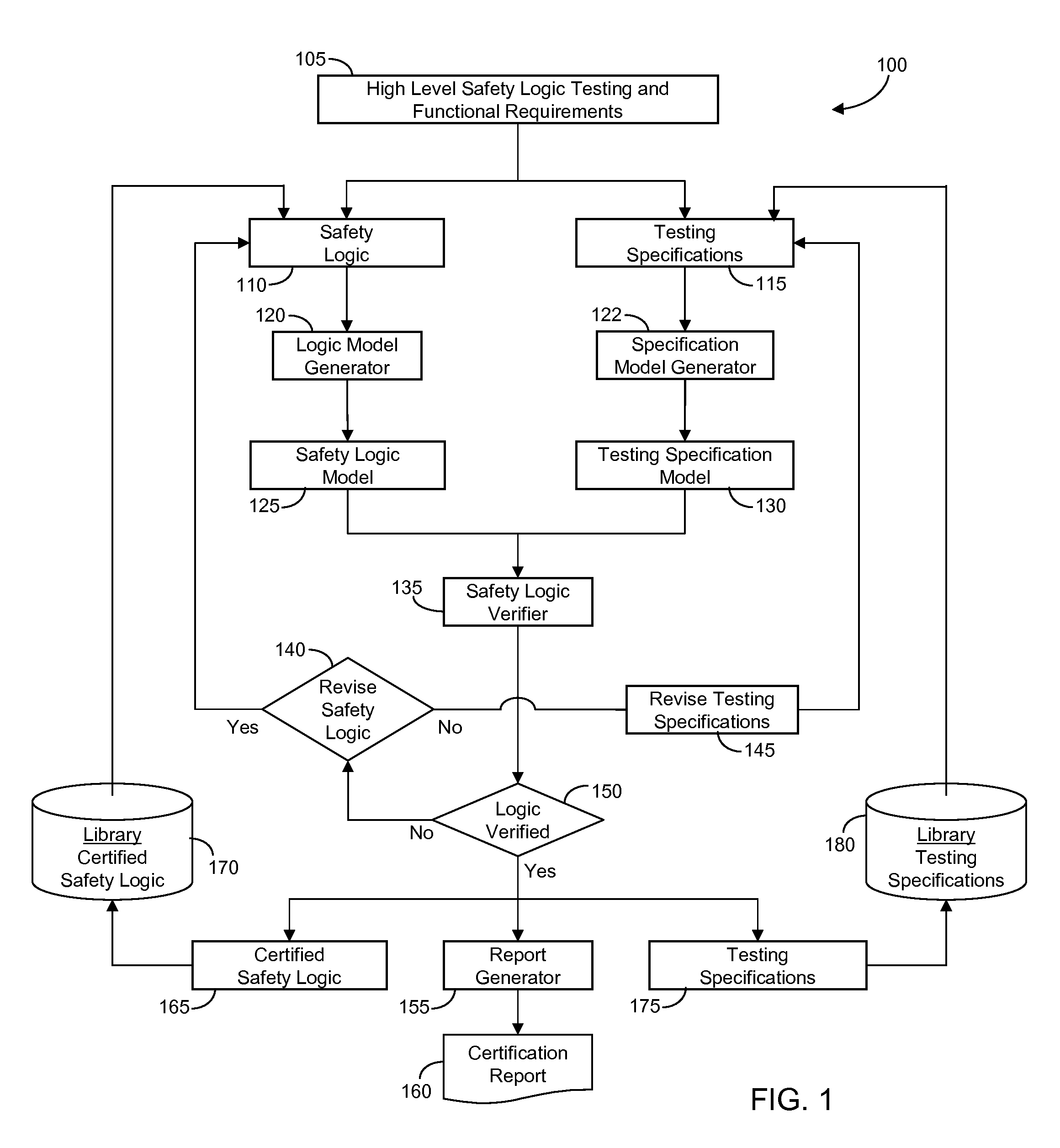
[0024]Referring to the drawings, and beginning with FIG. 1, generally indicated at 100 is a preferred embodiment of a system for the formal verification and certification of safety logic 110. Safety logic 110 is of the type typically used for control logic of safety-related systems in manufacturing cells, for example, in the logic of programmable logic controllers (PLC). The safety logic 110 may be stored in or provided through a controller, e.g., programmable logic controller (PLC) or accessible thereby, including the safety logic 110 as described below with reference to FIGS. 1-3. Safety logic 110 can be stored in ROM and automatically executed by a controller to provide the required functionality. The controller, e.g., PLC, may be configured as a digital computer having a microprocessor or central processing unit, read only memory (ROM), random access memory (RAM), electrically-erasable programmable read only memory (EEPROM), high speed clock, analog to digital (A / D) and digital ...


PUM


Abstract

A method and system is provided for verifying and certifying the safety logic of a manufacturing automation system including safety logic, where the logic may include one or more safety modules, routines, programs and tasks or a combination thereof; testing specifications corresponding to the safety logic; one or more formal model generators adapted for automatically transforming the safety logic and testing specifications through a logic parser into their respective mathematical models, formatted for example, as a Petri-net or binary decision diagram; a safety logic verifier configured for automatically comparing the safety logic formal model against the testing specification formal model to verify the safety logic model for the purpose of certifying the safety logic. The testing specifications may include testing of safety logic behavior including reaching safe state, remaining in safe state without reset, recovering from safe state with reset and remaining active with false alarm detection.

Description

TECHNICAL FIELD[0001]The invention relates generally to the testing of automation logic, and in particular to a computer executable method and system for formal verification of the safety-related automation logic that is used in a manufacturing cell.BACKGROUND OF THE INVENTION[0002]Automation logic, including safety-related logic that is used in a manufacturing cell, must be verified prior to implementation and deployment on the plant floor. A typical verification process requires setting up a hardware-based test-bed, which may be a prototype of the manufacturing cell and its safety control system. The physical safety components, for example, emergency stops, light curtains, gate and guard locks, safety mats and anti-tie down switches in the test-bed are connected to a safety automation controller or safety PLC through a safety network, which may be a separate network or integrated with the regular automation network. The automation logic to control the behavior of the physical safe...

Claims


Application Information

Patent Timeline
Patent Type & Authority Applications(United States)
IPC IPC(8): G06F19/00G06F11/36G05B9/02
CPCG06F11/3604G05B9/02
Inventor SETHURAMAN, NAGARAJANSCHROEDER, JEROME O.DE, SOUMENYUAN, CHENGYINBILLER, STEPHAN R.GAJOR, FRANKBYRNES, JEFFREY J.HUNSUR, NARAHARI K.
Owner GM GLOBAL TECH OPERATIONS LLC
Why Eureka
Try Eureka