Method for purifying a chlorine supply

a chlorine supply and purification technology, applied in the preparation of carboxylic acid halides, isocyanic acid derivative preparations, separation processes, etc., can solve the problems of nitrogen trichloride being sensitive to heat, sulfuric acid used to dry chlorine gas can sodium hydroxide that is typically used to form brine can also be contaminated with ammonia, etc., to achieve the effect of increasing safety, increasing energy efficiency, and increasing cost savings

Active Publication Date: 2011-06-16
BASF AG
View PDF10 Cites 14 Cited by
  • Summary
  • Abstract
  • Description
  • Claims
  • Application Information

AI Technical Summary

Benefits of technology

[0011]The method of this invention purifies the chlorine supply with increased energy efficiency, increased cost savings, and increased safety, thereby reducing environmental concerns. This method also efficiently separates chlorine gas from various by-products while simu...

Problems solved by technology

The formation of nitrogen trichloride typically occurs due to brine contamination, steam contamination, and/or water contamination.
Sodium hydroxide that is typically used to form the brine can also be contaminated with ammonia depending on purification processes.
In some cases, sulfuric acid used to dry the chlorine gas can be contaminated with ammonia.
As is well known in the art, nitrogen trichloride is sensitive to heat, light, sound, and shock and can quickly degrade at a rate sufficient to cause an explosion.
Accordingly, nitrogen trichloride is preferably removed from chlorine gas but is typically done so in a complex, time consuming, and expensive manner.
As is known in the art, when chlorine gas is used to synthesize phosgene, which in turn is used to synthesize isocyanates, presence of the carbon tetrachloride, nitrogen trichloride, and brominated compounds typically add color to the isocyanates which makes the isocyanates less commercially desirable.
However, use of these types of systems is very expensive, untimely, and complex.
In addition, the long lengths of pipes used in these systems only increase a number of p...

Method used


Image

  • Method for purifying a chlorine supply
  • Method for purifying a chlorine supply
  • Method for purifying a chlorine supply

Examples


Embodiment Construction

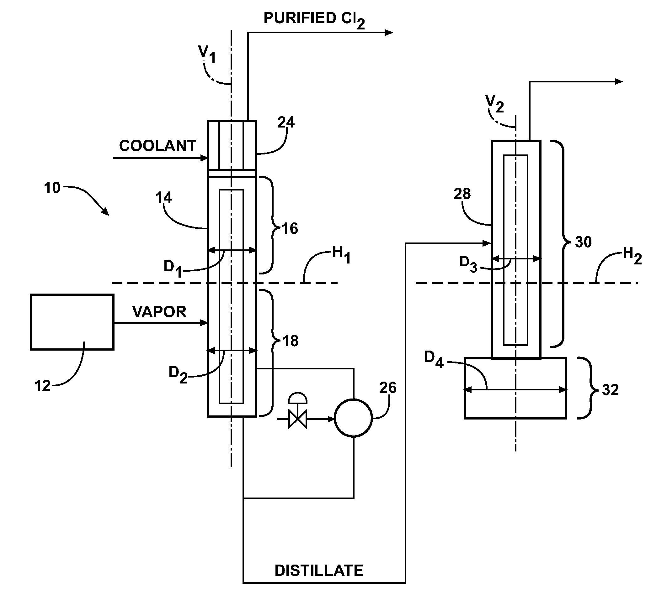
[0019]The present invention provides a method for purifying a chlorine (Cl2) supply and producing a purified chlorine gas (also known as an “overhead stream” in the art) in a distillation system (10). The purified chlorine gas is formed via distillation / fractionation procedures. The chlorine supply is not particularly limited and is not dependent on any particular method of formation. The chlorine supply may include liquid chlorine (Cl2(I)) or gaseous chlorine (Cl2(g)) such as those types used in commercial or industrial applications. The chlorine supply (also known as a “feed in” in the art) may be a finite supply or a continuous supply and may be provided from continuous or batch chlorine supply processes and / or in discrete units, such as from commercial tanker trunks or locomotive tanks. In one embodiment, the chlorine supply is provided in a semi-batch process. Typically, the chlorine supply is provided as a liquid via a pipeline to one or more storage locations and then purifie...


PUM

PropertyMeasurementUnit
Temperatureaaaaaaaaaa
Percent by massaaaaaaaaaa

Abstract

This invention provides a method for purifying a chlorine supply that includes a chlorine component, a bromine component, and nitrogen trichloride. The method includes the steps of introducing the chlorine supply into a vaporizer, heating the chlorine supply in the vaporizer to form a vapor, and introducing the vapor into a distillation system to provide purified chlorine gas, a distillate that includes liquid chlorine and the bromine component, and a bottoms component including the nitrogen trichloride. The method also includes the steps of condensing the vapor in a reflux condenser, heating the condensate in a reboiler, removing the purified chlorine gas from the distillation system, and removing the distillate from the distillation system.

Description

CROSS-REFERENCE TO RELATED APPLICATION[0001]The subject patent application claims priority to, and all the benefits of, U.S. Provisional Patent Application Ser. No. 61 / 261,176 filed on Nov. 13, 2009. The entirety of this provisional patent application is expressly incorporated herein by reference.FIELD OF THE INVENTION[0002]The present invention generally relates to a method for purifying a chlorine supply including a chlorine component, a bromine component, and nitrogen trichloride. More specifically, the method includes utilizing a particular distillation system to form purified chlorine gas and to decompose the nitrogen trichloride.DESCRIPTION OF THE RELATED ART[0003]Chlorine gas is typically commercially produced using one or more well known electrolysis processes such as mercury cell electrolysis, diaphragm cell electrolysis, membrane cell electrolysis, and / or electrolysis of fused chloride salts according to the Downs Process. The electrolysis processes typically produce chlor...

Claims


Application Information

Patent Timeline
IPC IPC(8): B01D3/02C07C51/58C07C263/10B01D5/00B01D3/34C01B32/80
CPCB01D3/148B01J2219/32C01B31/28C01B7/075C01B7/0743C01B32/80B01J19/24C01B7/07C01B7/0706
Inventor DOERR, ROBERT A.GAGNON, STEVEN D.BORDELON, KENNETH K.JACOBS, JOHANNES D.GRZANKA, THOMAS A.
Owner BASF AG
Why Eureka
Try Eureka