This helps you quickly interpret patents by identifying the three key elements:
Problems solved by technology
Method used
Benefits of technology
Benefits of technology
[0010]At least one of the needs and objectives that will become apparent from the following description is achieved in the present invention which comprises a process for producing substantially C5
Problems solved by technology
Their major limitation is that they do not produce gasoline mixtures, only predominantly diesel-range mixtures, those being mostly paraffinic and aromatic hydrocarbons with a C10 to C15 carbon skeleton.
Much research and effort has been undertaken to modify the original Fischer-Tropsch process to produce the gasoline-range mixtures, those having a C5 to C12 carbon skeleton, but to no avail.
However, this route is not as desirable as a chemical synthesisroute because the bacterial culturing, care and feeding of the converting bacteria is more art than science.
As a further disadvantage to this route of gasoline synthesis, there are large thermal inefficiencies owing to the large amount of water which must be externally heated as required to complete the process and maintain the bacteria.
Method used
Image
Click on the blue label to locate the original text in one second.
Reading with bidirectional positioning of images and text.
Examples
example 1
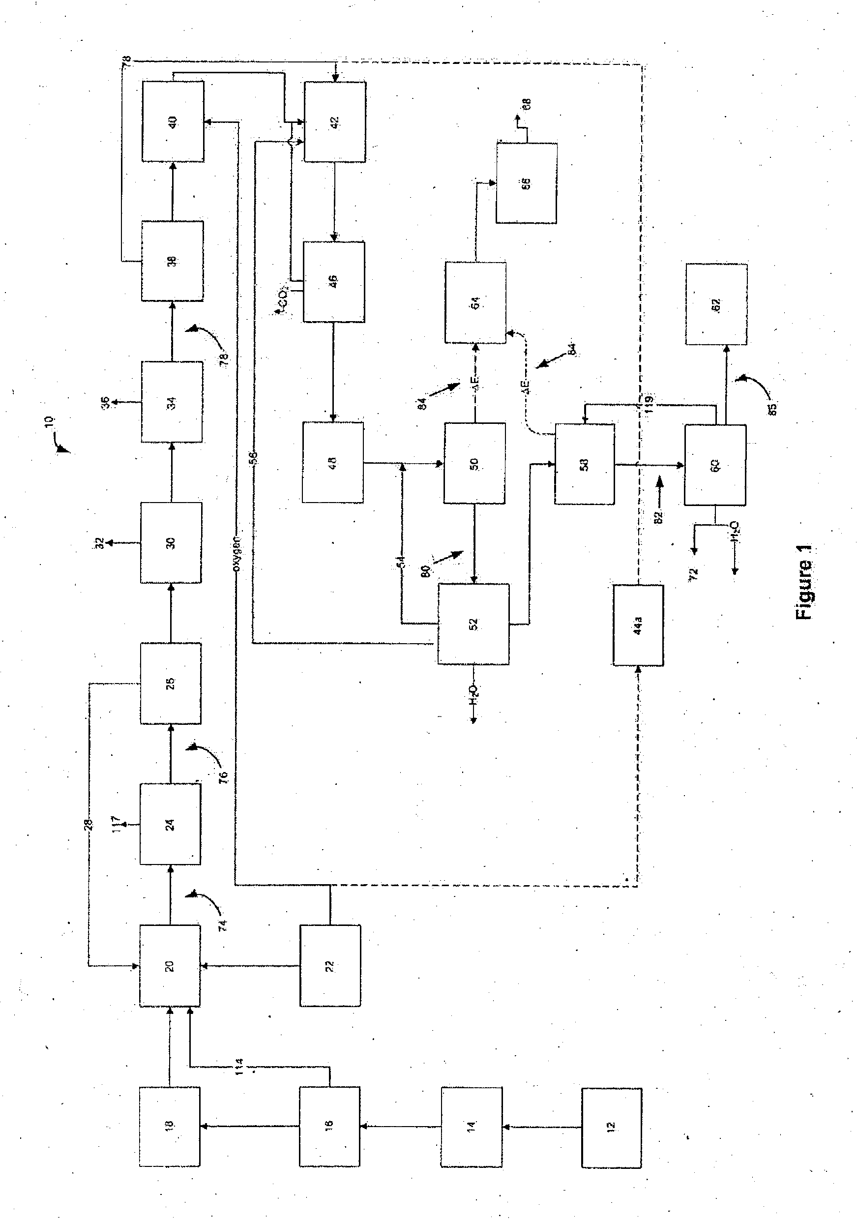
[0053]The primary elements of the process for producing liquid and gaseous hydrocarbons, plus water, of the present invention is shown generally at 10 in the block diagram of FIG. 1. In this diagram, solid organic material such as wood is utilized as organic feedstock 12. In the following description, variations on the process are included.
[0054]Organic feedstock 12 is prepared to enter the heating device also herein referred to as the gasifier 20. The organize feedstock 12 can be comprised of any or a combination of vegetative material, components of household garbage, man-made organic compounds such as plastic or rubber or a described above. In a preferred embodiment, wood chips are prepared as described with reference to FIG. 1, by reducing in particle size 14 and drying 16 to suit uniform feeding and heating. Following preparation, the wood chips 12 are then fed into the heating device 20. The heating device 20, for example, may be, but not limited to, a fluidized bed gasifier, ...
example 2
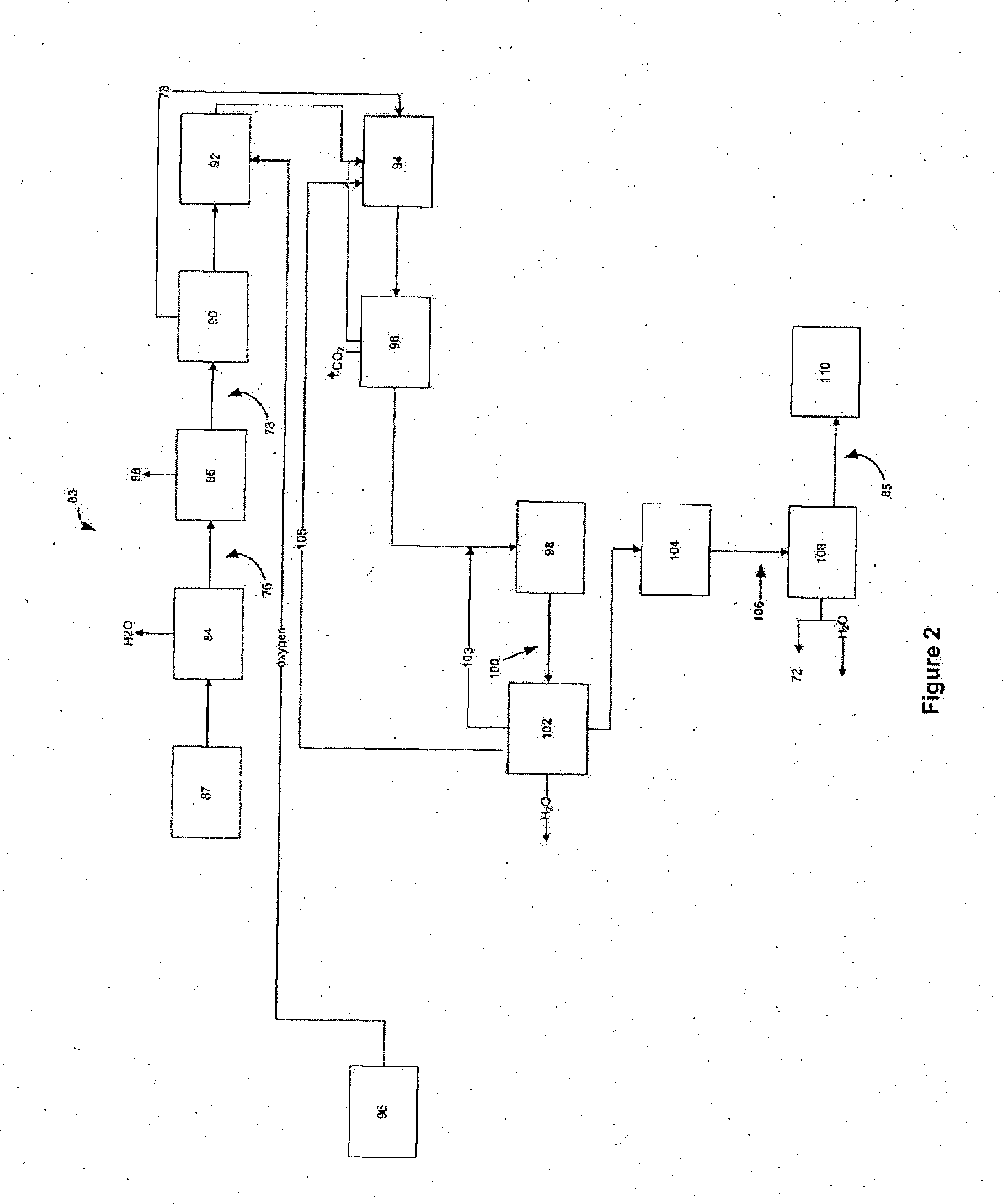
[0071]In an alternative embodiment disclosed in the present example, generally shown in FIG. 2 at 83, a gaseous organic feedstock 87 is utilized. For the purposes of the present example, the gas may be a single compound or a mixture of carbon-based organic gases. It should be understood that non-carbon-based gases and compounds may also be present in the gaseous organic feedstock 87 of the present example. For example, the gases referred to in the present example may be those resulting from the anaerobic digestion of manures or municipal sewagesludge, or landfill gas, which are likely to be or contain methane and carbon dioxide among other present compounds. By way of example of a single compound is propane, which may be the by-product of another process, can be utilized in an embodiment of the present example. The aforementioned gases are by way of examples; one skilled in the art will appreciate that many different possibilities exist for gaseous organic feedstock 87, which may a...
example 3
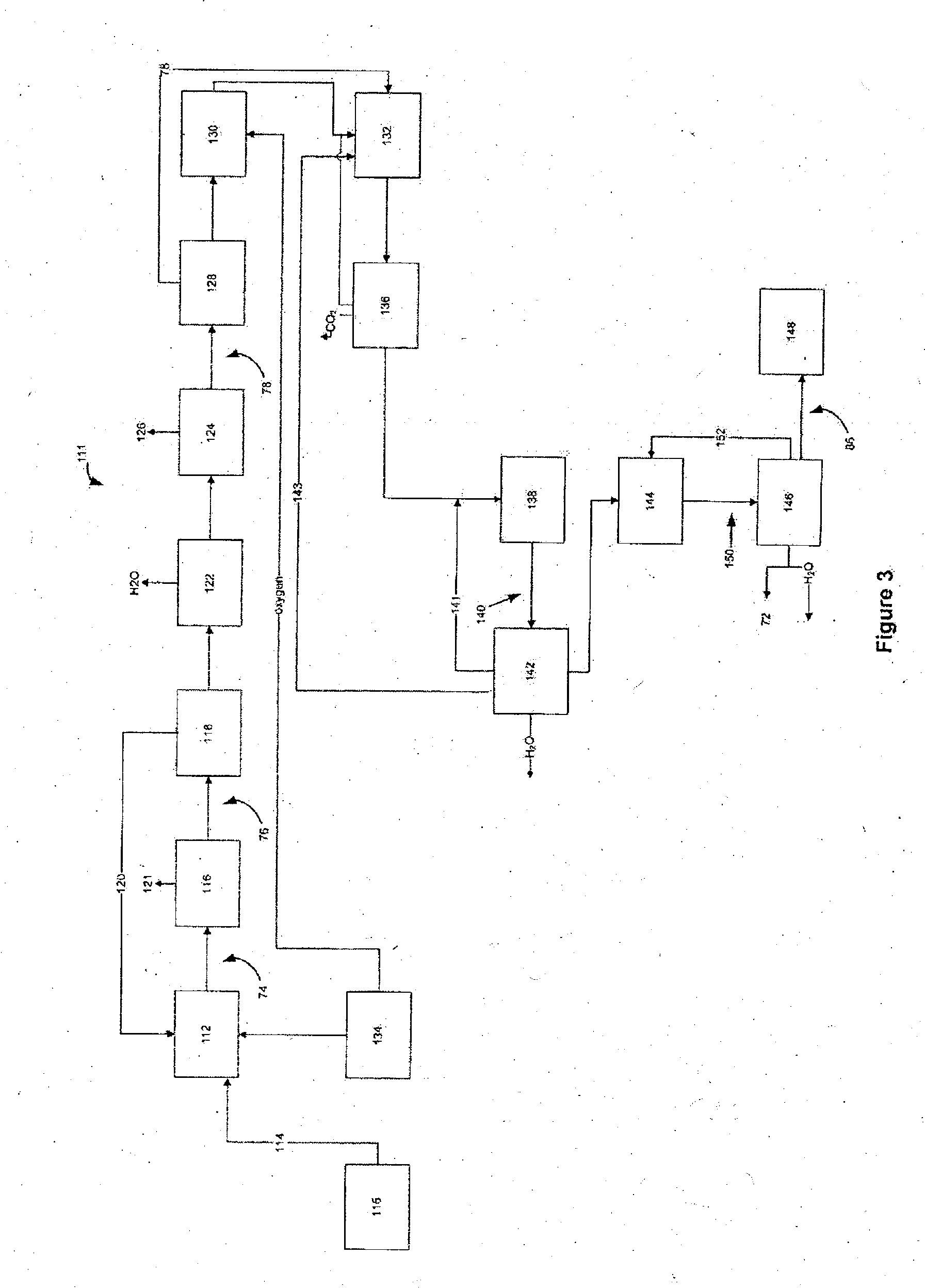
[0082]In an alternative embodiment disclosed in the present example, generally shown in FIG. 3 at 111, liquid organic feedstock 115 is processed. For exemplary purposes, the liquid organic feedstock 115 may be bio-oil from the pyrolysis of cellulosic material. Alternatively, or in combination with the preceding, the liquid organic feedstock 115 may be black or green liquour resulting from the processing of wood for the preparation of pulp. As will be readily appreciated, the most appropriate liquid organic feedstocks 115 will be generally known as liquids which are “carbon-rich”.
[0083]With reference to FIG. 3, the organic feedstock liquids 115 are fed into a heating device or gasifier 112. The heating device or gasifier 112 partially oxidizes liquid organic feedstock 115 to produce a synthesis gas 74 comprised primarily of carbon monoxide and hydrogen, but also may include carbon dioxide, hydrocarbons such as alkanes, alkenes or alkynes, suspended particulate matter, tars, or light ...
PUM
Property
Measurement
Unit
Temperature
aaaaa
aaaaa
Temperature
aaaaa
aaaaa
Temperature
aaaaa
aaaaa
Abstract
A process to efficiently convert organic feedstock material into liquid non-oxygenated hydrocarbons in the C5 to C12 carbon skeleton range is disclosed. The process can utilize gaseous, liquid or solid organic feedstocks containing carbon, hydrogen and, optionally, oxygen. The feedstock may require preparation of the organic feedstock for the process and is converted first into a synthesis gas containing carbon monoxide and hydrogen. The synthesis gas is then cleaned and conditioned and extraneous components removed, leaving substantially only the carbon monoxide and hydrogen. It is then converted via a series of chemical reactions into the desired liquid hydrocarbons. The hydrocarbons are suitable for combustion in a vehicle engine and may be regarded a replacement for petrol made from fossil fuels in the C5 to C12 carbon backbone range. The process also recycles gaseous by-products back through the various reactors of the process to maximize the liquid hydrocarbon in the C5 to C12 carbon skeleton range yield.
Description
RELATED APPLICATION[0001]The present application is related to and claims benefit of priority to U.S. Provisional Application No. 61 / 124,869 entitled “A Process for Producing Gasoline From Carbonaceous Feedstock” filed Apr. 21, 2008, the disclosure of which is hereby fully incorporated by reference.FIELD OF THE INVENTION[0002]The present invention is related to a process for producing hydrocarbons for use as a fuel. Specifically, the present invention is related to the production of non-oxygenated hydrocarbons having a C5 to C12 carbon skeleton produced via a dimethyl ether catalytic reaction from synthesis gas.BACKGROUND OF THE INVENTION[0003]Fuel for vehicles has been produced in the past from the refining of crude oil. The refining process results in gasoline, jet fuel and diesel fuel. This source has been the mainstay of fuel for our transportation systems since the 1800s.[0004]In 1955, synthetic oil was first produced from coal by Sasol, a South African group of companies in th...
Claims
Application Information
Patent Timeline
Application Date:The date an application was filed.
Publication Date:The date a patent or application was officially published.
First Publication Date:The earliest publication date of a patent with the same application number.
Issue Date:Publication date of the patent grant document.
PCT Entry Date:The Entry date of PCT National Phase.
Estimated Expiry Date:The statutory expiry date of a patent right according to the Patent Law, and it is the longest term of protection that the patent right can achieve without the termination of the patent right due to other reasons(Term extension factor has been taken into account ).
Invalid Date:Actual expiry date is based on effective date or publication date of legal transaction data of invalid patent.

