
Apparatus for feeding antenna elements and method therefor

an antenna array and antenna technology, applied in the direction of frequency measurement arrangement, instruments, measurement devices, etc., can solve the problems of less suitable for miniaturization and monolithic integration in modern submicron ic technology, and not readily available in baseline integrated technology

Active Publication Date: 2011-06-30
NXP BV
View PDF7 Cites 10 Cited by
  • Summary
  • Abstract
  • Description
  • Claims
  • Application Information

AI Technical Summary

Benefits of technology

[0004]Accordingly, it is one object of the present invention to provide an apparatus for feeding antenna elements with dimensions and structures such that the apparatus can be miniaturized quite well and is suitable for monolithic integration in submicron technology.
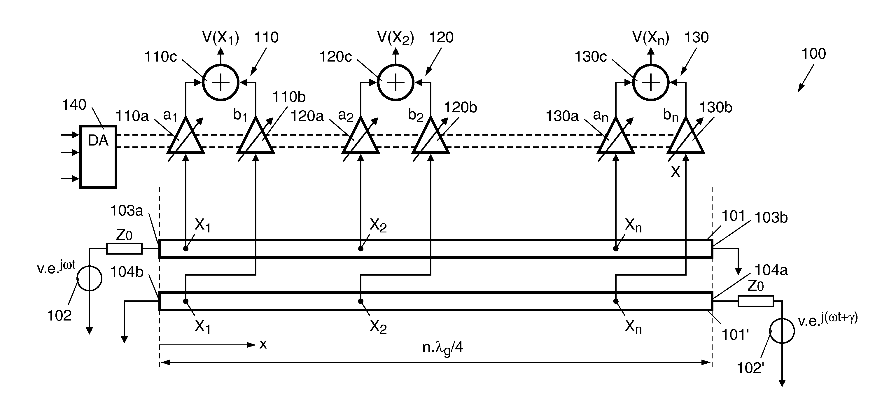
[0007]Since a pair of transmission lines of the apparatus operate as resonators with a respective physical length of a quarter wavelength of the operating frequency, the plurality of electronic circuits provided in the apparatus detect and process signals from corresponding measuring positions on the resonators, wherein the measured signals are a function of amplitude- and phase angle relations at the respective measuring position due to local energy concentrations stored in the resonators as standing wave. Thus, the output signals generated by the electronic circuits reflect the amplitude- and phase relations on the transmission lines at the respective position and can be used as driving signals for antenna elements or as LO (local oscillator) signals for an up conversion mixer between the electronic circuits and the corresponding antenna elements. Due to the small physical length of the resonators the apparatus has the advantage that it can be miniaturized quite well and is suitable for monolithic integration in submicron integrated circuit technology. In addition, the losses are not critical since the transmission lines are configured to be before the electronic circuits.
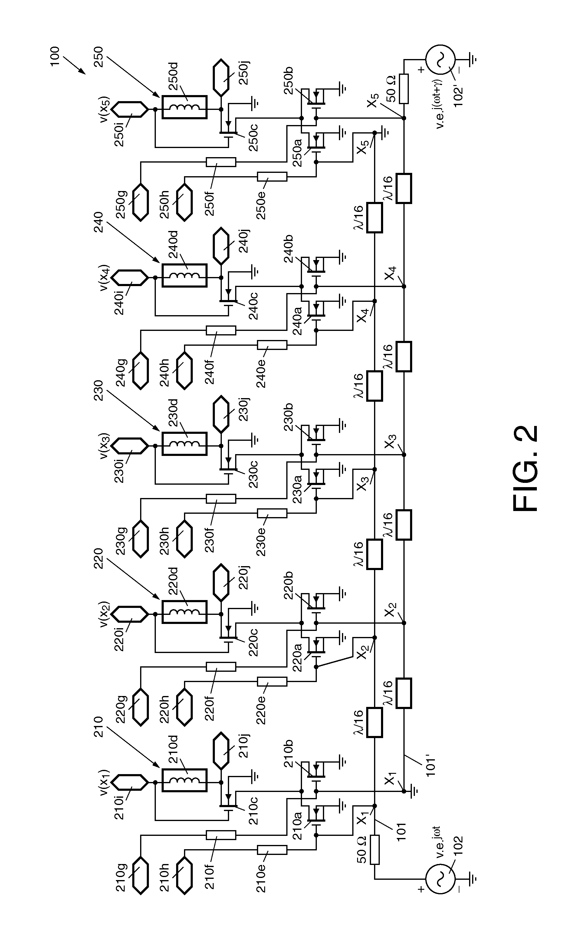
[0017]In an embodiment the amplification circuits are realized as field effect transistor circuits and the amplifiers are realized as common source stages, the inputs thereof are coupled to a corresponding measuring position pair and the outputs thereof are coupled to an input of the summing element configured as common gate stage. The realization of the circuitry by use of field effect transistors allows high frequency and low noise application of the apparatus according to the invention. As an advantage the apparatus is suitable for operation at frequencies close to the maximum frequency of the active devices, since parasitic reactance of the input impedance of the active devices can be absorbed in the transmission line resonators.
[0018]In an embodiment at least one pair of transmission lines is provided and signals from respective measuring positions of the transmission line pair are detected and amplified by corresponding amplification circuits, and summed such that output signals of the transmission line pair from a respective measuring position are added as steering signals for corresponding antenna elements in a one-dimensional linear antenna array. In the case of a two-dimensional planar antenna array a second transmission line pair is fed with a signal of different phase angles and the output signals of the both transmission line pairs are summed, resulting to the generation of a pencil beam with independent control of perpendicular phase angles.
[0019]To sum up, the inventive apparatus has the following advantages: An advantage is that the apparatus is suitable for operation at frequencies close to the maximum frequency of the active devices. The parasitic reactance of the input impedance of the active devices can be absorbed in the transmission line resonators. In addition, since all multiplication coefficients can be selected positive, the amplifiers do not have to switch between inverting and non-inverting operation, which limits normally the parasitic loading of output nodes. A further advantage is that the apparatus can operate at high power efficiency and / or low noise which makes it possible to combine the phase shifting function with the power amplifier or low noise amplifier function. The use of straightforward gain controlled amplifiers avoids the waste of energy in biasing complex multiplier circuits, which is important for the power amplifier efficiency and allows optimization for low noise, which is important for the low noise amplifier function. A still further advantage is that the apparatus provides high resolution phase and amplitude control so that the signal distortion due to incoherent signal summation is limited. The high-resolution control allows accurate calibration of the various signal paths to compensate for process spread and temperature effects. Continuous control is obtained with analog control signals, the resulting resolution in case of digital control is determined by that of the Digital-to-Analog Converter. Accurate phase and amplitude control is further simplified by using just two transmission lines which avoids the occurrence of scan angle dependant phase and amplitude errors due to undesired electromagnetic coupling between transmission lines.

Problems solved by technology

Since such a switched transmission line concept requires at least a half wave line length per antenna element, this type of structure requires at least this size in two dimensions, making it less suitable for miniaturization and monolithic integration in modern submicron IC technology.
Furthermore, in order to limit RF losses, this type of passive structure requires a high quality RF (radio frequency) switch or varactor technology, which is not readily available in baseline integrated technologies.

Method used


Image

  • Apparatus for feeding antenna elements and method therefor
  • Apparatus for feeding antenna elements and method therefor
  • Apparatus for feeding antenna elements and method therefor

Examples


Embodiment Construction

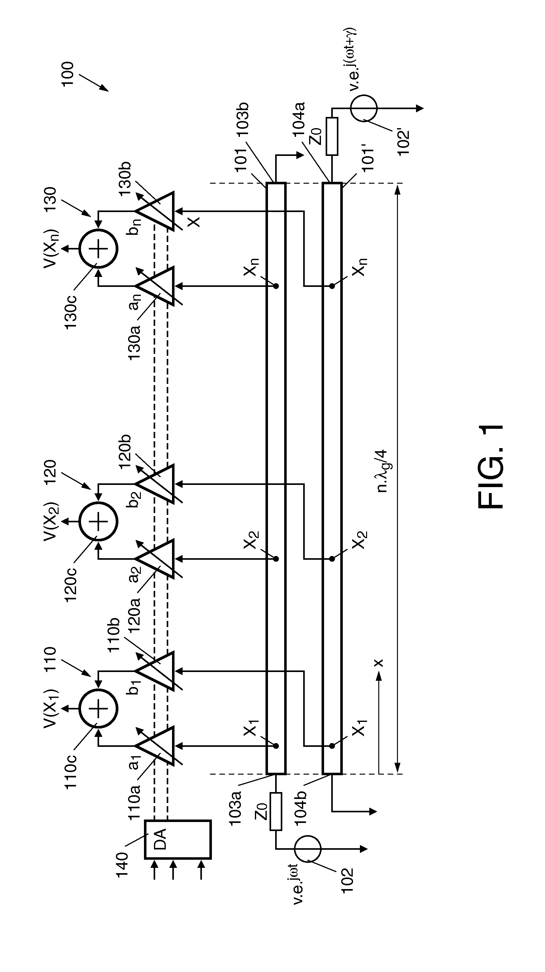
[0030]FIG. 1 illustrates schematically the apparatus 100 according to the invention comprising a first transmission line 101 and a second transmission line 101′ which are disposed in parallel along their longitudinal direction x and spaced in a direction transverse to the longitudinal direction; two high-frequency (HF) signal sources 102, 102′ coupled to the transmission lines and operated at a certain frequency ω; further a plurality of amplification circuits 110, 120, 130 the inputs thereof coupled to the two transmission lines 101, 101′ in regular intervals along their longitudinal direction x and outputs thereof are used for feeding antenna elements. For controlling the amplification circuits 110, 120, 130 a Digital-to-Analog Converter DAC 140 is provided, with its analog control signals the respective amplification circuits 110, 120, 130 are controllable. The respective outputs of the amplification circuits 110, 120, 130 are used for feeding antenna elements (not shown) of a ph...


PUM


Abstract

An apparatus (100) for feeding antenna elements of a phased array antenna, comprises: at least two transmission lines (101, 101) disposed in parallel and operated at a certain frequency as resonators, each of the transmission lines (101, 101) having a predetermined length dimensioned to be at least approximately an electrical quarter-wavelength of the operating frequency, a plurality of measuring positions provided on the transmission lines (101, 101) in spacings along the longitudinal direction (x) of the transmission lines, wherein each measuring position on one of the two transmission lines (101) faces directly a corresponding neighbored measuring position on the other transmission line (101) and such corresponding measuring positions being adjacent to each other in a direction transverse to the longitudinal direction of the transmission lines (101, 101) form a measuring position pair, respectively, wherein each of the circuits (110, 120, 130) detects and amplifies / attenuates the measuring signals from an assigned measuring position pair associated with the transmission lines (101, 101) for a corresponding longitudinal position as a function of a resonant field in the transmission lines at the respective positions, and further adds the measured and processed signals in order to generate output signals for feeding corresponding antenna elements.

Description

FIELD OF THE INVENTION[0001]The present invention relates in general to an apparatus for feeding antenna elements of an antenna array. In particular, the present invention relates to a system comprising the apparatus and an antenna array. More particular, the present invention relates to a method for operating the apparatus for feeding antenna elements.[0002]Such apparatuses serve to accomplish radiation pattern control of a phased array antenna, where the term phased array antenna means an array of multiple antenna elements with the phase and also the amplitude of each antenna element being a variable, providing control of the radiation pattern, in particular the beam direction.BACKGROUND OF THE INVENTION[0003]A known apparatus to provide beam steering of a phased array antenna is the so-called Butler matrix which is a matrix transmission network with a considerable number of transmission lines or cables where beam steering is accomplished by switching the signal paths between the ...

Claims


Application Information

Patent Timeline
IPC IPC(8): G01R23/08
CPCH01Q3/34H01Q21/0075H01Q3/42
Inventor DE GRAAUW, ANTONIUS JOHANNES MATHEUS
Owner NXP BV
Learn More