
Stainless steel material for a separator of a solid polymer fuel cell and a solid polymer fuel cell using the separator

a solid polymer fuel cell and separator technology, applied in the direction of cell components, superimposed coating process, cell component details, etc., can solve the problems that each technique has a technical problem to be solved, cannot be an alternative to gold plating technique, etc., to achieve small degradation of cell performance, high economic efficiency, and high energy generation performance

Inactive Publication Date: 2011-06-30
NIPPON STEEL CORP
View PDF26 Cites 11 Cited by
  • Summary
  • Abstract
  • Description
  • Claims
  • Application Information

AI Technical Summary

Benefits of technology

[0053]The term “oxide film located on the surface of the stainless steel base metal” means a passivation layer disposed on the surface of the stainless steel. Because of this passivation film, the corrosion resistance of a separator can increase during the operation of a fuel cell.
[0093]A solid polymer fuel cell having a high performance in generation of energy, a small degradation of cell performance, and a high degree of economic efficiency is provided by using the separator according to the present invention, since the separator does not need costly surface treatment such as gold plating in its preparation.

Problems solved by technology

However, none of these techniques has been put to practical use.
It is thought that each of these techniques has a technical problem to be solved.
Therefore, this technique cannot be an alternative to gold plating.
Above-described method (B) has problems such as paint stripping during assembly of a fuel cell and paint stripping caused by swelling and shrinking of an MEA (Membrane-Electrode Assembly) accompanying starting and stopping of a fuel cell, since the adhesion of the resulting electroconductive paint film to the substrate is not sufficient.
Above-described method (C) cannot be used for mass production, since thin-film deposition technologies are costly and take a long time for deposition.

Method used

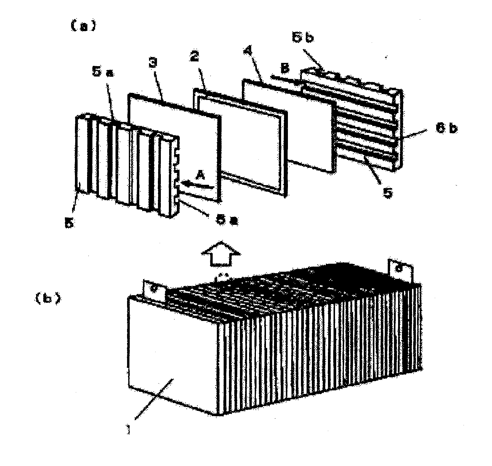
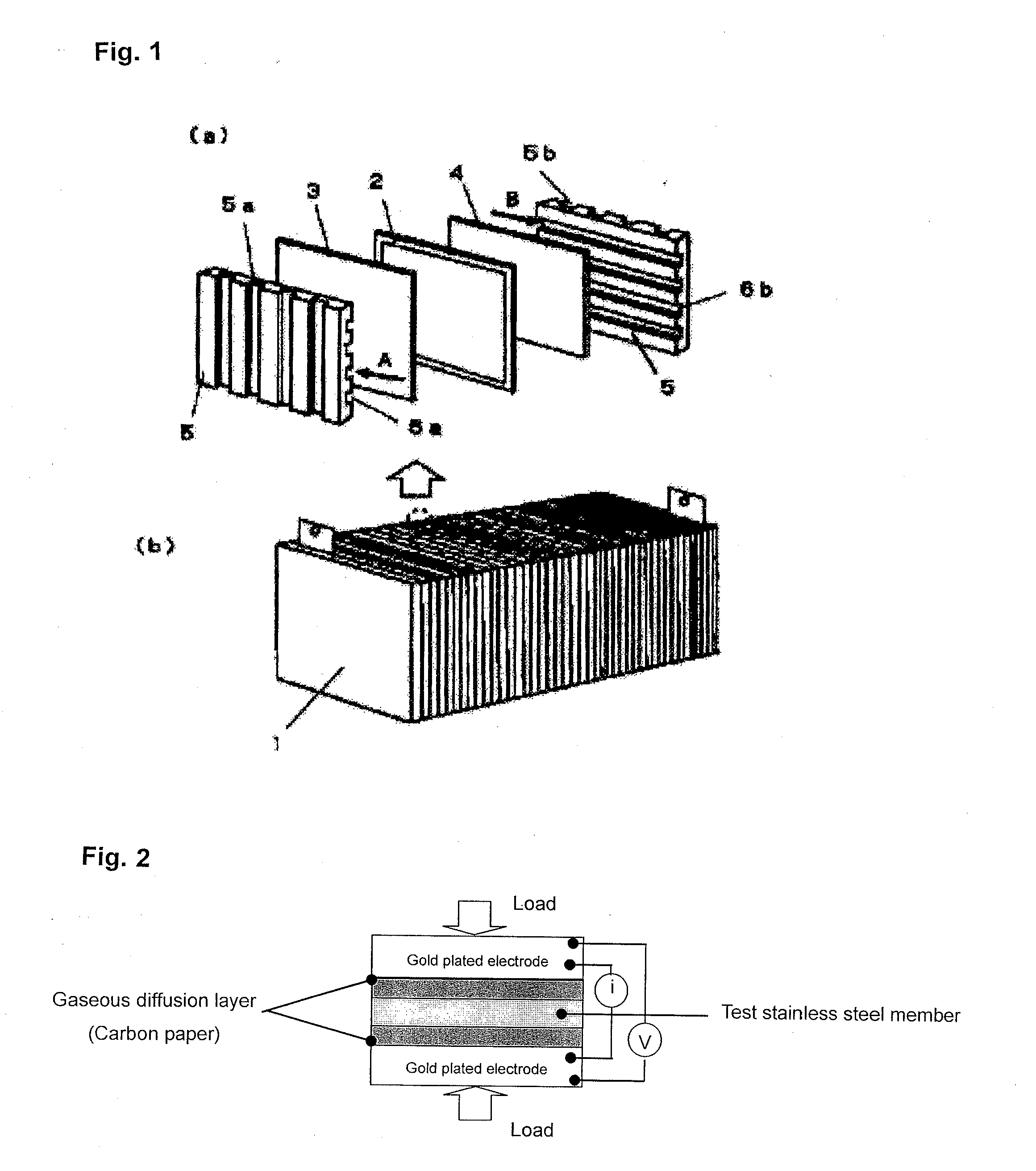
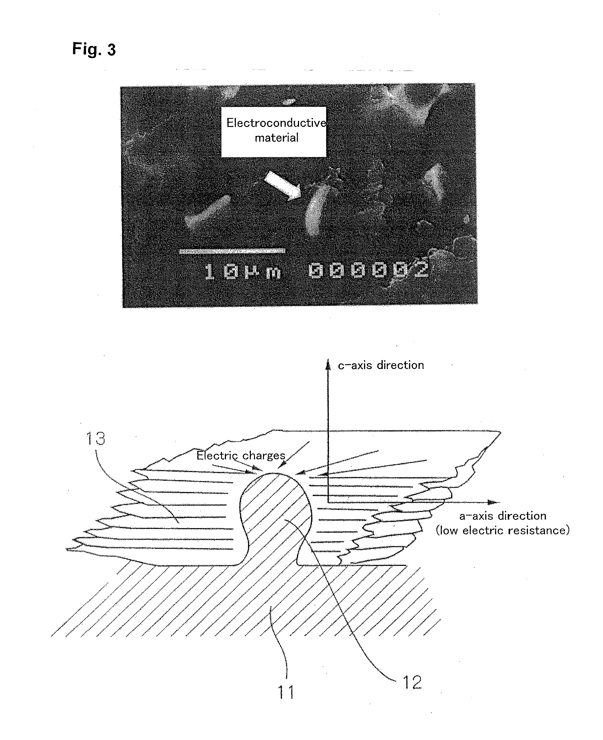

Image

  • Stainless steel material for a separator of a solid polymer fuel cell and a solid polymer fuel cell using the separator
  • Stainless steel material for a separator of a solid polymer fuel cell and a solid polymer fuel cell using the separator
  • Stainless steel material for a separator of a solid polymer fuel cell and a solid polymer fuel cell using the separator

Examples


example 1

[0174]Examples for illustrating the superiority of the present invention are shown below. While the nonmetallic electroconductive material in the following examples comprises graphite, the nonmetallic electroconductive material need not comprise graphite as long as the material has low electric resistance.

[0175]1. Preparation of a Member Formed of Stainless Steel

[0176](1) Preparation of a Stainless Steel Plate

[0177]Each of ten different stainless steels having the chemical composition shown in Table 1 was melted in a 150 kg-vacuum furnace which could heat steel by high-frequency induction heating to obtain an ingot. The character “A” in the column for steel type in Table 1 means an austenitic stainless steel, and the character “F” in the column means a ferritic stainless steel.

TABLE 1Chemical composition (% by weight, balance consisting of Fe and inevitable impurities)MaterialCSiMnPSCuCrNiMoVAlNBSteel typePrecipitationmaterial 10.0220.3501.000.0220.0010.4521.0011.002.20—0.0100.0250....

examples 1 , 4

Examples 1, 4, and 7 of Present Invention

[0230]The surfaces of a sheet member for a separator on which M2B-type borides were precipitated and which would contact gaseous diffusion electrode layers during the operation of a fuel cell were covered with graphite by sliding a block of graphite having a rectangular contact surface measuring 100 mm by 100 mm on the sheet member. The block of graphite was a product of Toyo Tanso Co., Ltd. and the graphite had a lattice spacing d002 of 3.36 angstroms.

examples 2 and 6

of Present Invention

[0231]The surfaces of a sheet member for a separator on which M2B-type borides were precipitated and which would contact gaseous diffusion electrode layers during the operation of a fuel cell were coated with a paint composition obtained by 15-fold dilution of a liquid dispersion of PTFE (POLYFLON D1 produced by Daikin Industries, Ltd.) with pure water. The resulting sheet member was dried to form coating films on the surfaces of the sheet member for a separator. Each of the surfaces of this sheet member having the coating films was then made to slide on a block of graphite having a rectangular contact surface measuring 100 mm by 100 mm, so that the surface of the sheet member for a separator was covered with an adhesive agent and graphite. The block of graphite was a product of Toyo Tanso Co., Ltd. and the graphite in the block has a lattice spacing d002 of 3.36 angstroms.


PUM

PropertyMeasurementUnit
lattice spacingaaaaaaaaaa
Ra roughnessaaaaaaaaaa
thicknessaaaaaaaaaa

Abstract

A stainless steel member comprising a stainless steel base metal; an oxide film located on the surface of the stainless steel base metal; an electroconductive layer located on the surface of the oxide film and comprising a nonmetallic electroconductive material; and an electroconductive material which is located so as to penetrate the oxide film and which electrically contacts the stainless steel base metal and the electroconductive layer is provided as a stainless steel member for a separator of a solid polymer fuel cell having excellent properties such that a degradation in performance is low even after prolonged operation. A solid polymer fuel cell using the stainless steel member is also provided.

Description

TECHNICAL FIELD[0001]The present invention relates to a solid polymer fuel cell and a stainless steel for a separator which is a component of the fuel cell.BACKGROUND ART[0002]A fuel cell is a next-generation power generation system which is expected to be installed and widely used from the viewpoints of energy conservation and concern for the environment, since a fuel cell utilizes energy generated during a reaction combining hydrogen and oxygen. There are several types of fuel cells including a solid electrolyte type, a molten carbonate type, a phosphoric acid type, and a solid polymer type.[0003]A solid polymer fuel cell has gathered particular attention for use as a power source for an electric vehicle and a dispersed power source for household use, since a solid polymer fuel cell can be easily downsized because of its high power density, and it is easy to start and stop because of its relatively low operating temperature compared to other types of fuel cell.[0004]FIG. 1 shows a...

Claims


Application Information

Patent Timeline
Patent Type & Authority Applications(United States)
IPC IPC(8): H01M8/24H01M2/16H01M8/10
CPCC21D6/002C23C28/048C22C38/02C22C38/04C22C38/42C22C38/44C22C38/54C23C28/00C23F17/00H01M8/021H01M8/0213H01M8/0228H01M2008/1095Y02E60/50C23C28/042C22C38/001
Inventor KAMINAKA, HIDEYAIMAMURA, JUNKOHIGASHIDA, YASUTO
Owner NIPPON STEEL CORP
Learn More