
Method for inspecting bolts

a bolt and bolt body technology, applied in chemical methods analysis, instruments, structural/machine measurement, etc., can solve the problems of increased initial cost and running expense, difficult to increase the strength of the material proposed, and difficult to use the proposed material as the bolt material

Inactive Publication Date: 2011-07-07
MITSUBISHI HEAVY IND LTD
View PDF4 Cites 0 Cited by
  • Summary
  • Abstract
  • Description
  • Claims
  • Application Information

AI Technical Summary

Benefits of technology

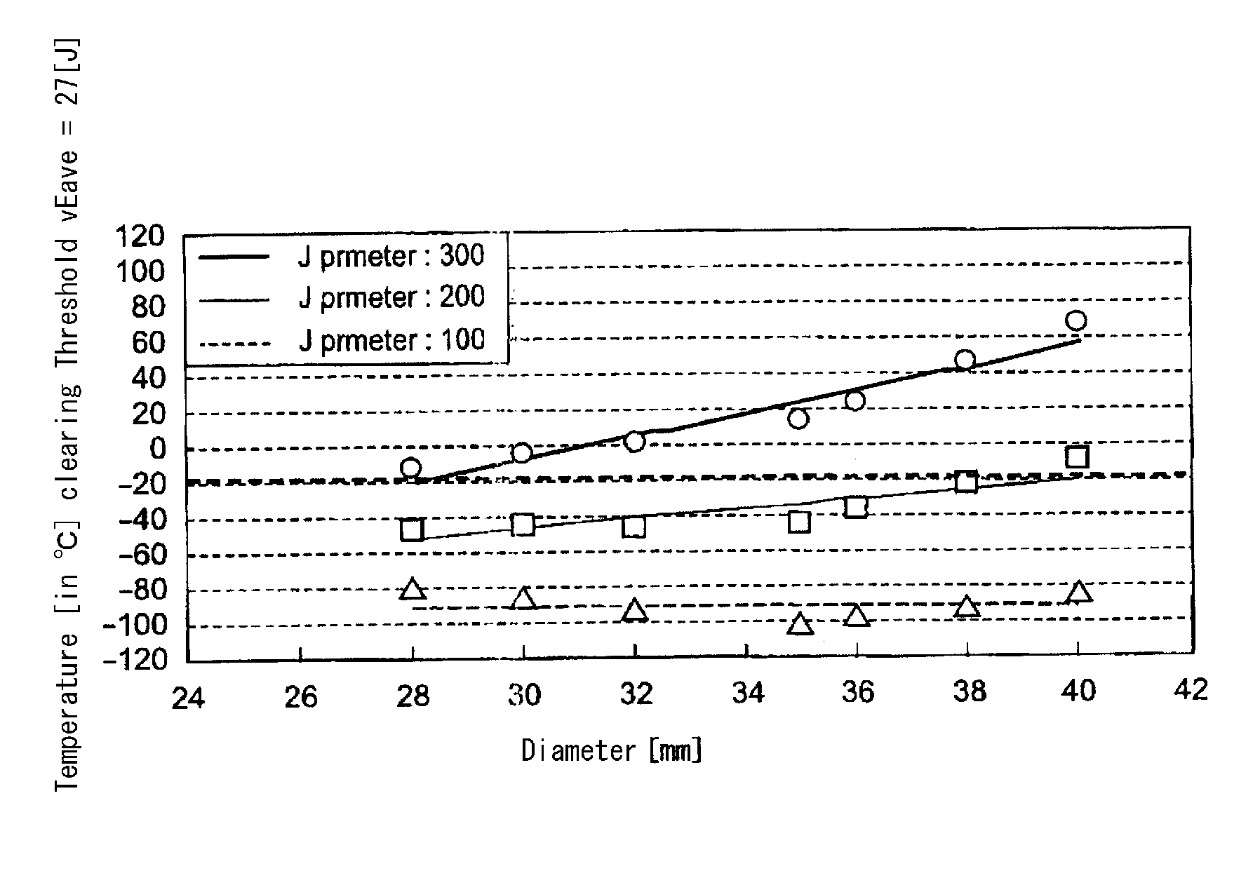
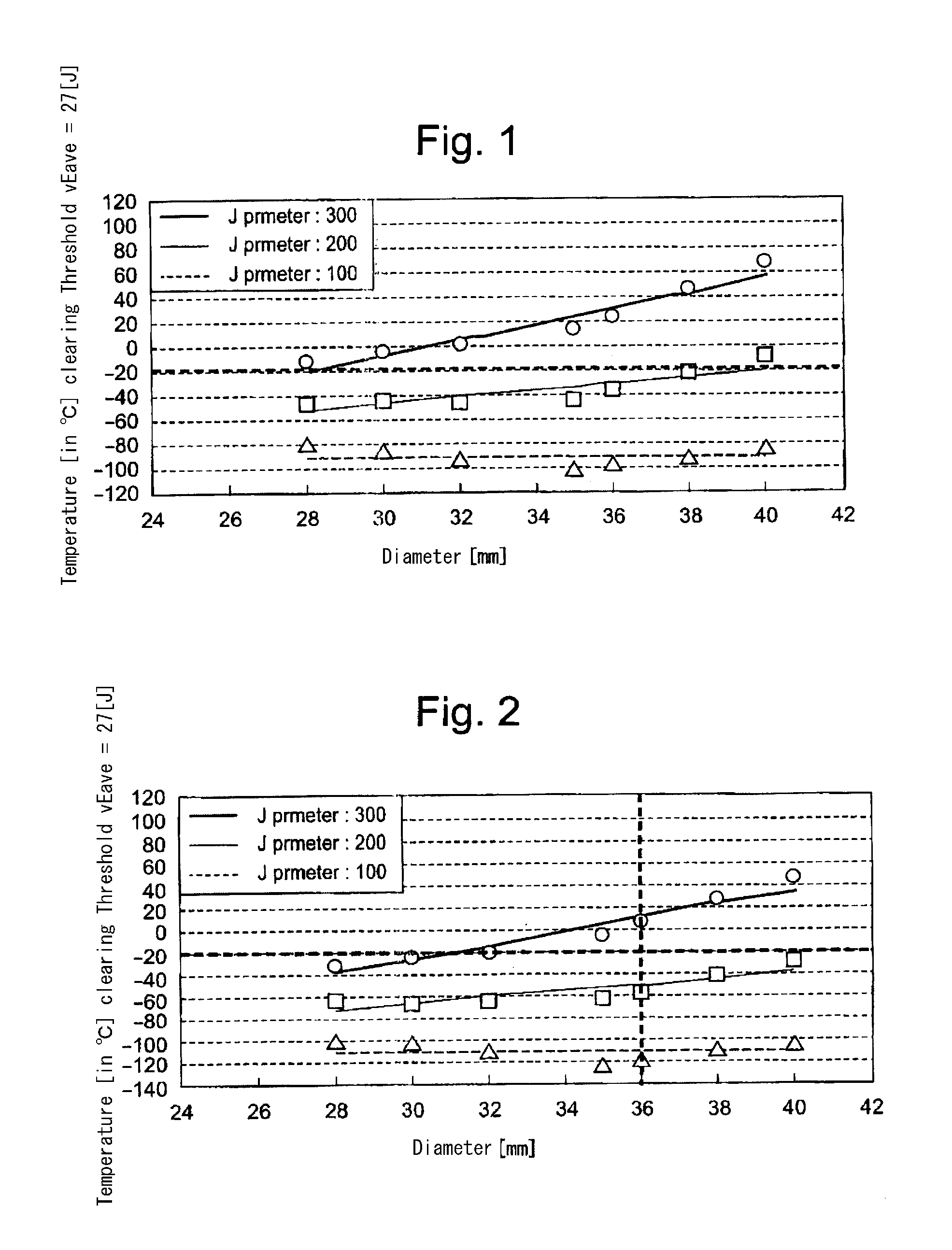
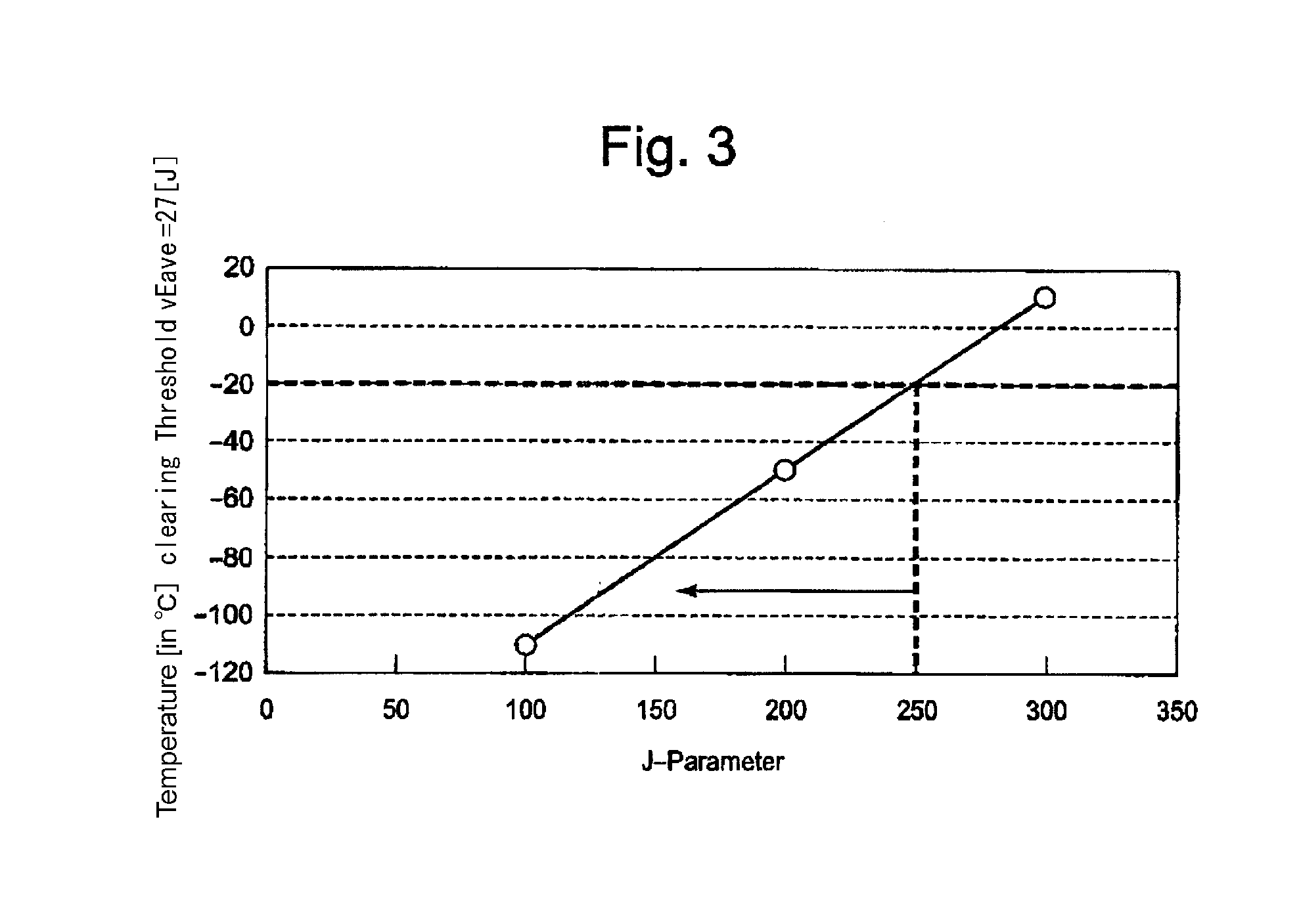
[0034]By judging whether or not the bolt is usable for the cold climate condition on the basis of the J parameter and the diameter of the bolt, the time-consuming Charpy impact test that includes complicated processes can be dispensed with; accordingly, the bolt inspection time can be reduced and the series of the work processes can be simplified.
[0035]Further, in calculating the J parameter, the values regarding the silicon (Si) percentage content, the manganese (Mn) percentage content, the phosphorus (P) percentage content and the tin (Sn) percentage content in mass % are used, thereby the values are described in the steel material inspection certificate; accordingly, from a bolt manufacturer's standpoint, the analysis of the steel material components can be dispensed with. Hence, The J parameter can be calculated in a shorter time.
[0039]When the maximum diameter regarding the bolts is specified, whether or not each bolt is usable for the cold climate condition can be judged on the basis of the calculated J parameter. Thus, the bolt inspection time can be further reduced.

Problems solved by technology

However, in order to produce the martensitic stainless steel that is disclosed in the patent reference 1, a plenty amount of chromium has to be added in the crystal structure; thereby, the precipitation and growth of ferrous temper carbide that enhances the strength of the material of the bolt steel cannot be easily expected; thus, it is difficult to increase the strength of the material proposed in the patent reference 1.
Hence, it is difficult to use the proposed material as the bolt material in relation to the wind turbine installed in cold climate areas.
Further, if a material to be usable for the bolt of the wind turbine installed in cold climate areas is used together with the chromium molybdenum steel as a material of the bolt for the wind turbine installed in non-cold climate areas, then it becomes necessary to manufacture the two kinds of materials in separated facilities; hence, the initial cost as well as the running expense increases.
Accordingly, in order to perform a Charpy impact test, the sampled bolt sampled out of the production lot of the bolts has to be cut so as to manufacture the test piece of the prism shape; thus, complicated and time-consuming work is required in preparing the test piece.
Hence, performing the Charpy impact test for the chromium molybdenum steel bolts and classifying the chromium molybdenum steel bolts into two classes (i.e. the usable bolt and the unusable bolt for the cold climate condition) on the basis of the result of the Charpy impact test require the work for hours; and, the complicated work processes become necessary.
Moreover, there is another problem; according to the above-described approach in which whether or not the manufactured chromium molybdenum steel bolts are usable for the cold climate condition by use of the Charpy impact test, the judgment as to whether or not the bolts of the lot are usable cannot be made until the Charpy impact test is finished.
Further, since the ratio of the number of the usable bolts to the number of the whole manufactured bolts is not clear before the Charpy impact test is performed, it cannot be judged whether or not a necessary number of the bolts that are usable for the cold climate is prepared; in some cases, a necessary number of the bolts cannot be prepared in time for the construction work of the wind turbine.

Method used


Image

  • Method for inspecting bolts
  • Method for inspecting bolts
  • Method for inspecting bolts

Examples


Embodiment Construction

[0049]Hereafter, the present invention will be described in detail with reference to the embodiments shown in the figures. However, the dimensions, materials, shape, the relative placement and so on of a component described in these embodiments shall not be construed as limiting the scope of the invention thereto, unless especially specific mention is made.

[0050]The inventors of the present invention have made researches on the factors that have effects on the Charpy impact values of the material of the bolt made of chromium molybdenum steel, the contents [in mass o] of the material being:

[0051]carbon (C) content of more than or equal to 0.33% and less than or equal to 0.38%,

[0052]silicon (Si) content of more than or equal to 0.15% and less than or equal to 0.35%,

[0053]manganese (Mn) content of more than or equal to 0.60% and less than or equal to 0.85%,

[0054]chromium (Cr) content of more than or equal to 0.90% and less than or equal to 1.20%,

[0055]molybdenum (Mo) content of more th...


PUM

PropertyMeasurementUnit
temperatureaaaaaaaaaa
temperaturesaaaaaaaaaa

Abstract

A testing method for the bolt to be used under the conditions of excessive wind force by which bolts made of Cr—Mo steel can be separated into a group of bolts usable in cold areas and a group of bolts unusable in cold areas without conducting Charpy impact test involving complicated operation, specifically, a testing method for determining whether bolts made of heat-treated Cr—Mo steel are usable or unusable in cold areas, wherein the determination is conducted on the basis of both J parameter calculated by formula: J=(Si %+Mn %) (P %+Sn %) 104 (wherein P %, Si %, Mn % and Sn % are contents (mass %) of phosphorus (P), silicon (Si), manganese (Mn) and tin (Sn) respectively as disclosed in the inspection certificate of the Cr—Mo steel) and bolt diameter.

Description

FIELD OF THE INVENTION[0001]The present invention relates to an inspection method for inspecting bolts, especially the bolts that are to-be-used for a wind turbine installed in cold climate areas; thereby, in the inspection method, it can be estimated whether or not the bolt as an object of the inspection can be used for the wind turbine.BACKGROUND OF THE INVENTION[0002]The bolts used for the wind turbine for wind power generation need to be of high strength and of sufficient toughness. Hence, as a steel material of the bolt used for the wind turbine, the chromium molybdenum steel that is of high strength and of sufficient toughness is often used. The chromium molybdenum steel is special alloy steel made from iron (Fe), carbon (C), chromium (Cr) and molybdenum (Mo); namely, the chromium molybdenum steel has the material contents, chromium (Cr) and molybdenum (Mo) in the carbon steel (Fe+C) that includes carbon (C) beside the base content iron (Fe); adding the chromium elements to st...

Claims


Application Information

Patent Timeline
Patent Type & Authority Applications(United States)
IPC IPC(8): G06F19/00
CPCC22C38/02C22C38/22C22C38/04C22C38/008G01M13/00G01N33/20
Inventor NAKAYAMA, SHINTADA, MASUONUMAJIRI, TOMOHIRO
Owner MITSUBISHI HEAVY IND LTD
Learn More