Detection system and method

a detection system and detection method technology, applied in the field of diagnostics, can solve the problems of constructive limitation of the combination of improved optical readout and magnetic actuation, and achieve the effects of simple low-cost magnetic system, enhanced surface specificity, and enhanced detection sensitivity

Active Publication Date: 2011-07-14
SIEMENS HEALTHINEERS NEDERLAND BV
View PDF11 Cites 22 Cited by
  • Summary
  • Abstract
  • Description
  • Claims
  • Application Information

AI Technical Summary

Benefits of technology

[0014]The arrangement according to the invention enables and makes use of magnetically activated displacement of captured targets towards a detection surface, selective excitation of these captured targets at the detection surface from and detection the response of the excitation in order to know the presence of the target. This surface localized excitation gives an enhanced surface specificity, so that a sensitivity enhancement in detection is achieved. The invention combines the advantages of surface detection with a simple low cost magnetic system for bringing the target to the surface. The magnetic system provides a high speed transport mechanism. In addition, both excitation and detection are done from one side of the detection surface so that a compact construction of the device is achieved. Accordingly, the device can be produced as a low cost compact arrangement by providing a fixed magnet and radiation guidance system. Magnetic actuation allows attracting beads towards (up-concentration) and away from (washing) the surface efficiently, while the dimensions of the beads ensure that strong radiation signals can be generated.
[0015]In an embodiment the excitation radiation is evanescent with the advantage to have increased selectivity of excitation at the detection surface. A magnetic field guide arrangement is preferably provided for focusing the magnetic field from the magnet to the analysis region. This enables the magnet to be located away from the analysis region, so that there is sufficient space for the magnet and the excitation source and detector.
[0016]The magnetic field guide arrangement can be arranged in a horse-shoe configuration (essentially a linear arrangement), with the collected radiation passing down the centre of the field guide to the detector. This provides a compact arrangement. The radiation coupling arrangement can then provide the excitation radiation to the analysis region up the central opening of the horse-shoe field guide arrangement, and has a radiation coupling arrangement for focusing the radiation onto the analysis region to generate the evanescent radiation in the sample. The radiation coupling arrangement can then also be for focusing the collected radiation to the detector, and the radiation coupling arrangement can comprise a beamsplitter for providing different radiation paths for the collected radiation and the excitation radiation. This provides a compact combined excitation and detection radiation system, partly housed within the centre of the annular magnetic field guide.

Problems solved by technology

Thus there is a practical constructive limitation for the combination of improved optical read out and magnetic actuation when related to a device suitable for point of care use.

Method used


Image

  • Detection system and method
  • Detection system and method
  • Detection system and method

Examples


second embodiment

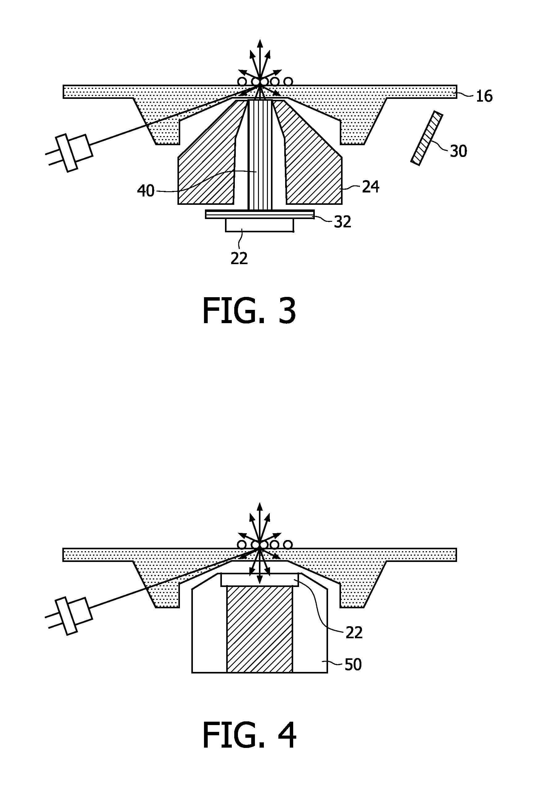
[0052]In a second embodiment shown in FIG. 3, the emitted light is transported from the analysis region by a light guide 40, for example fibre bundles. The detector 22 is placed at the lower end of the light guide 40 outside the magnetic head. This enables a more compact design of the magnetic field guides and allows the use of standard components for the optical elements.

third embodiment

[0053]In a third embodiment shown in FIG. 4, the photodetector 22 is positioned directly on top of the magnet 50 that is used for actuation of the magnetic labels. The photodetector 22 is still however located in the reader instrument to keep costs of the disposable part of the apparatus low. FIG. 4 shows a flat underside of the substrate in the analysis region, but an optical component such as a single refractive or diffractive lens, or a 1D- or 2D-lenslet array (providing imaging functionality), could again be moulded in the bottom of the optical substrate to increase the collection efficiency, as shown in FIG. 2.

[0054]To keep the photodetector slim, it is preferably a semiconductor element (e.g. photodiode, CCD, CMOS) or a polymeric element.

[0055]Excitation by total internal reflection as shown in the examples above can be replaced by excitation with an evanescent light guide, as shown in FIG. 5. In this way, no components are required at the location of the analysis region for c...


PUM


Abstract

A detection system combines an excitation radiation source (18) providing excitation radiation (10) to an analysis region of a sample (14) within a substrate (16) having a detection surface, a detector (22) for detecting radiation collected from the analysis region comprising the detection surface of the sample resulting from the excitation, and a magnet arrangement (24) beneath the analysis region of the sample, and stationary with respect to the excitation radiation source and light coupling arrangement, for attracting magnetic beads (15) within the sample to the substrate surface The detection radiation is collected from the detection surface of the substrate, to give an enhanced surface specificity The invention combines the advantages of surface detection with a simple low cost magnetic system for bringing the target to the surface

Description

FIELD OF THE INVENTION[0001]The invention relates to detection systems and methods, particularly in the field of diagnostics.BACKGROUND OF THE INVENTION[0002]One example of a detection system is based on creation of fluorescence radiation in a sample that may be detected to analyse the sample with respect to its constitution, and an example of the use of fluorescence detection is in nucleic acid testing (NAT). This is a core element in molecular diagnostics for detecting genetic predispositions for diseases, for determining RNA expression levels or identification of pathogens, like bacteria and viruses that cause infections. Such bio-sensing methods can also be used to detect other analytes such drugs (therapeutic or abuse) or markers for disease in bodily fluids such as for example blood, urine or saliva.[0003]The detection of fluorescence can be used both for a qualitative or a quantitative determination of the presence of a particular target analyte in a sample (e.g. DNA, protein...

Claims


Application Information

Patent Timeline
Patent Type & Authority Applications(United States)
IPC IPC(8): G01J1/58
CPCG01N21/648G01N21/6428
Inventor WIMBERGER-FRIEDL, REINHOLDNIEUWENHUIS, JEROEN HANSSCHLEIPEN, JOHANNES JOSEPH HUBERTINA BARBARA
Owner SIEMENS HEALTHINEERS NEDERLAND BV
Why Eureka
Try Eureka