
Nerve stimulator and method using simultaneous electrical and optical signals

Active Publication Date: 2011-07-14
VANDERBILT UNIV +1
View PDF99 Cites 53 Cited by
  • Summary
  • Abstract
  • Description
  • Claims
  • Application Information

AI Technical Summary

Benefits of technology

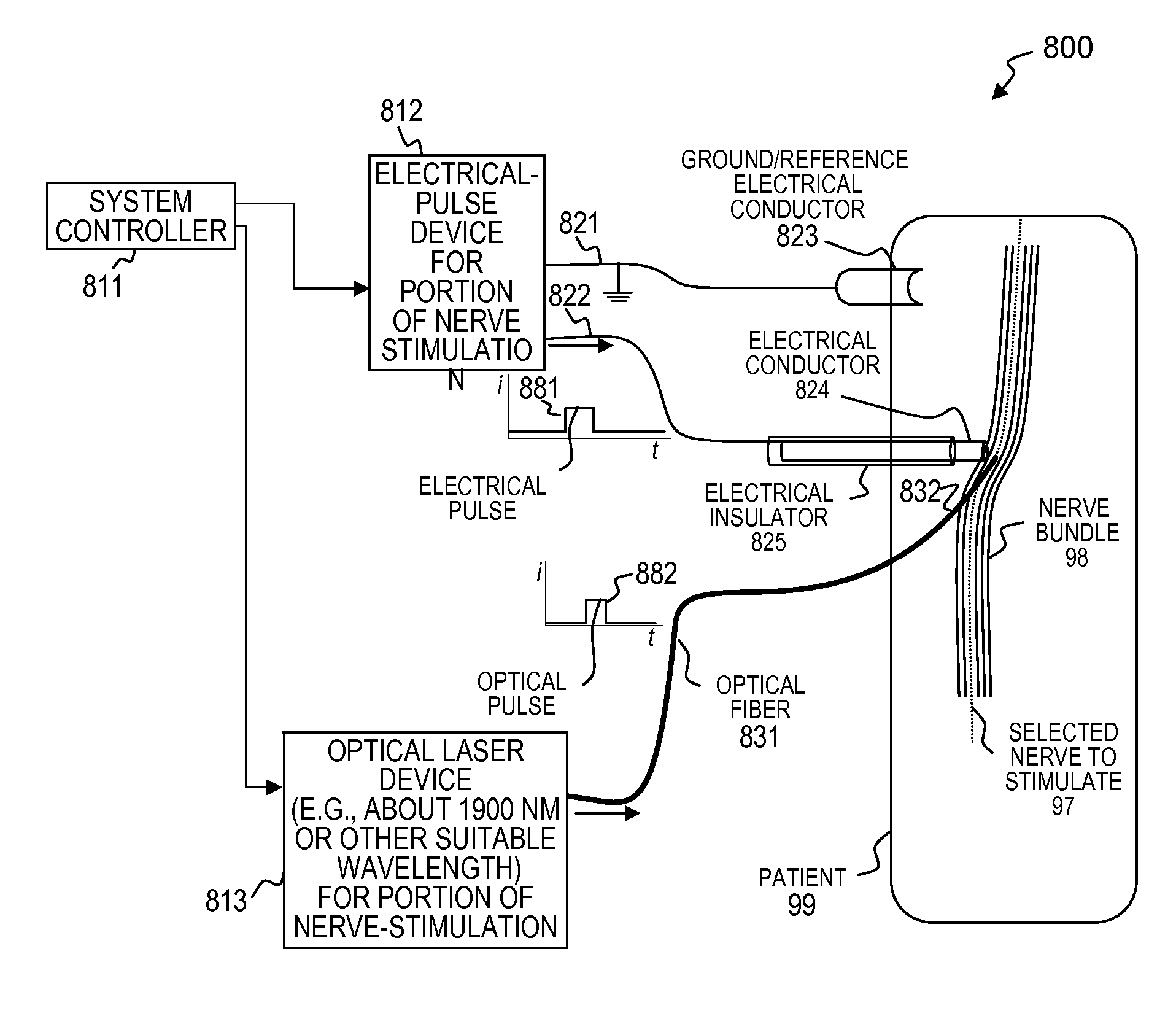
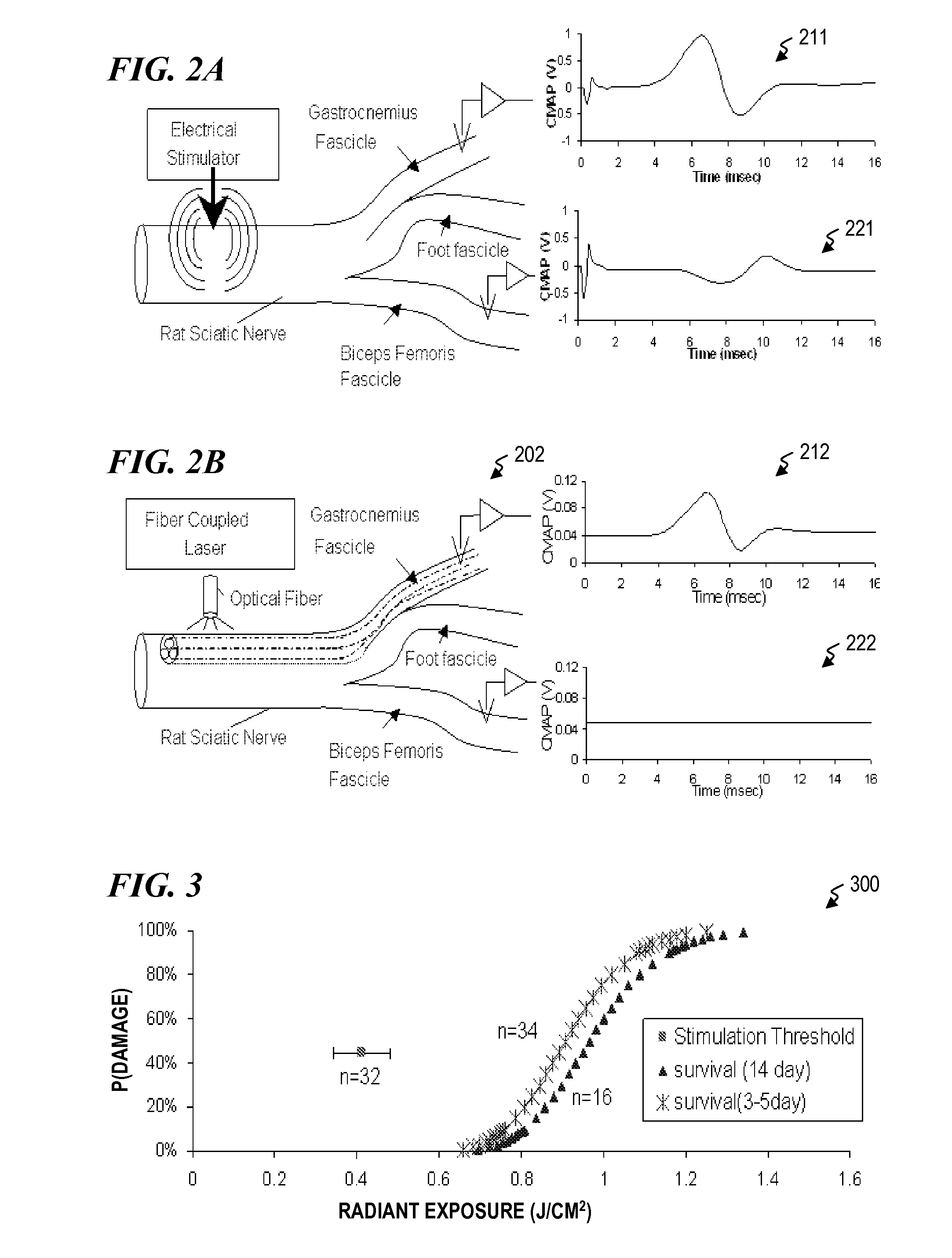
[0032]The present invention provides apparatus and methods some or all of which may be combined in various embodiments for stimulating animal tissue (for example to trigger a nerve action potential signal in nerves of a human patient) by application of both electrical and optical signals for treatment and diagnosis purposes. In some embodiments, the application of an electrical signal before or simultaneously (or, in some embodiments, after) the application of an optical signal allows the use of a lower amount of optical power or energy than would otherwise be needed if an optical signal alone were used for the same purpose and effectiveness. The application of the electrical signal may precondition the nerve tissue (electrically “priming” the excitable tissue making it more susceptible to stimulation and in particular optical stimulation (sodium and potassium channels are voltage sensitive, such that the probability of a channel opening or being open increases with increased voltage differential from the outside to inside of the cell; upon channel opening, positively charged ions (sodium) move from the extracellular to intracellular space, thus affecting the probability of open for neighboring channels; in some embodiments, the present invention adjusts the voltage increase the probability that a channel is open)) such that a lower-power optical signal can be used to trigger the desired NAP with substantially the same selectivity as seen with the stand-alone optical stimulation that otherwise would take a higher-power optical signal, were the electric signal not applied. In some embodiments, the hybrid combination of electrical and optical stimulation overcomes limitations of each modality, significantly reducing IRNS-threshold levels (order of magnitude) while retaining the highly precise stimulation of discrete axonal populations, thus achieving high spatial selectivity for nerve stimulation with clinically viable safety and efficacy thresholds. This also reduces the optical power requirements for laser devices that mediate the stimulation of neural tissues, thus making implantable laser-based neuroprostheses and neurostimulators more practical for human use or allows more channels using the same power budget (i.e., the power budget being, e.g., the amount of power used in an implantable device).

Problems solved by technology

One disadvantage of using electrical stimulation is that the electrical signal applied to stimulate one nerve fiber will generally stimulate a plurality of surrounding nerve fibers (even nerve fibers in other fascicles than the fascicle containing the nerve of interest) to also trigger NAP signals in those other nerve fibers: Present neuromodulation technology is based on the generation of electric fields around the neuron.
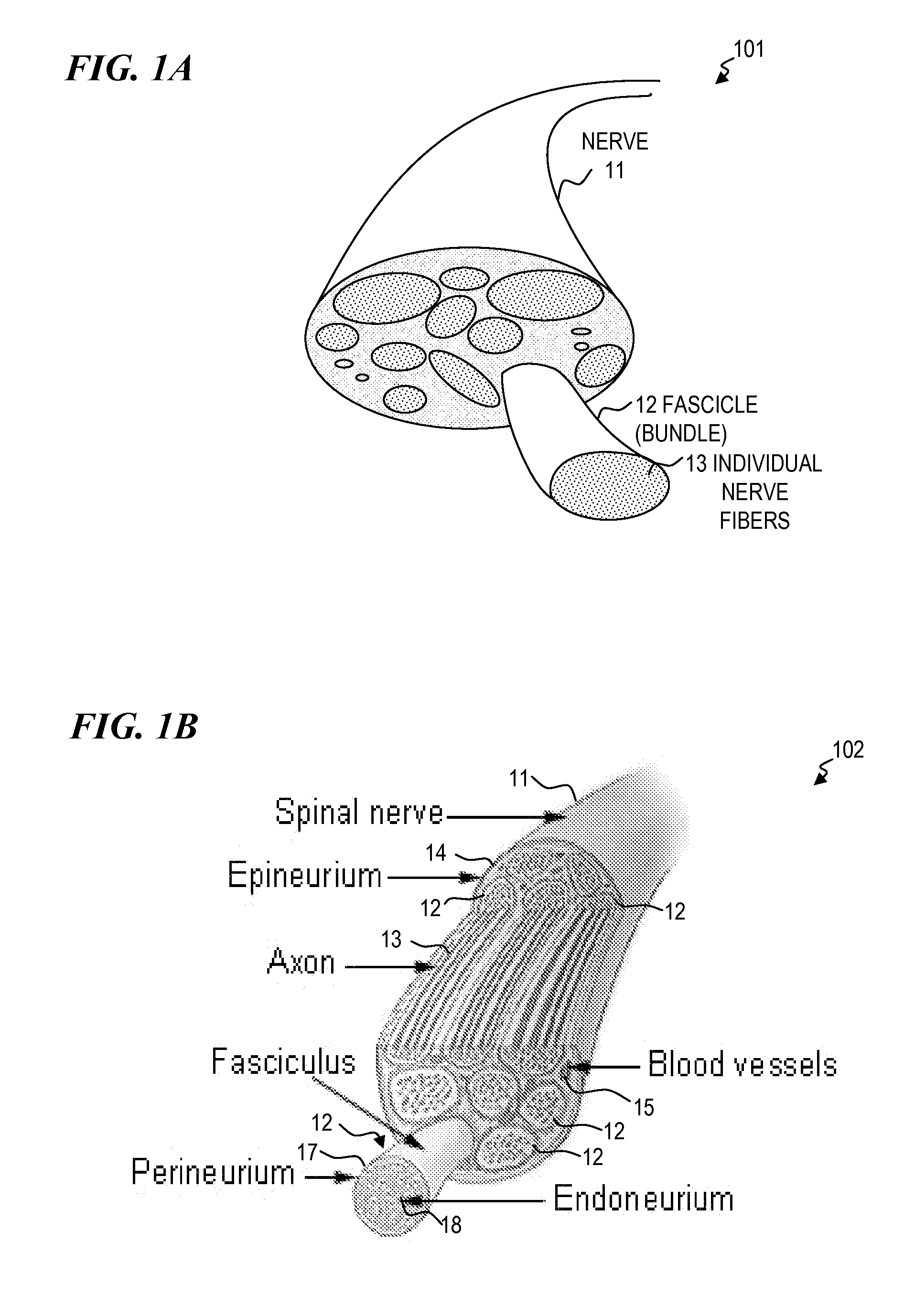
This causes the voltage distribution to be fairly uniform within at least a portion of a fascicle (while also being electrically isolated from neighboring fascicles), hence limiting the possibility of sub-fascicular selectivity when using electrical stimulation.
Electrical stimulation with the spiral and FINE electrode designs can be effective, but these electrode designs are limited in their ability to stimulate each of the forty-three (43) fascicles individually.
This has been demonstrated to be effective for selective stimulation, although there is evidence that this approach may cause damage to the nerve.
Violation of the perineurium typically compromises the blood-nerve-barrier and other protective mechanisms of the perineurium.
Although important advances in spatial selectivity have been made in electrical stimulation (described above), the precision of electrical-stimulation techniques is fundamentally limited by the fact that electrical current spreads in a conductive medium (e.g., within a fascicle, since the tissue providing primary electrical insulation to prevent loss is the perineurium that surrounds the fascicle at its perimeter).
At repetition rates greater than 5 Hz tissue-temperature changes will become additive with each ensuing laser pulse, and resulting tissue damage may begin to occur with prolonged constant stimulation.
Effective, specific and precise stimulation of selected nerves remains a problem.

Method used


Image

  • Nerve stimulator and method using simultaneous electrical and optical signals
  • Nerve stimulator and method using simultaneous electrical and optical signals
  • Nerve stimulator and method using simultaneous electrical and optical signals

Examples


Embodiment Construction

[0074]Although the following detailed description contains many specifics for the purpose of illustration, a person of ordinary skill in the art will appreciate that many variations and alterations to the following details are within the scope of the invention. Accordingly, the following preferred embodiments of the invention are set forth without any loss of generality to, and without imposing limitations upon the claimed invention. Further, in the following detailed description of the preferred embodiments, reference is made to the accompanying drawings that form a part hereof, and in which are shown by way of illustration specific embodiments in which the invention may be practiced. It is understood that other embodiments may be utilized and structural changes may be made without departing from the scope of the present invention.

[0075]The leading digit(s) of reference numbers appearing in the Figures generally corresponds to the Figure number in which that component is first intr...


PUM


Abstract

An apparatus and method for stimulating animal tissue (for example to trigger a nerve action potential (NAP) signal in a human patient) by application of both electrical and optical signals for treatment and diagnosis purposes. The application of an electrical signal before or simultaneously to the application of a NAP-triggering optical signal allows the use of a lower amount of optical power or energy than would otherwise be needed if an optical signal alone was used for the same purpose and effectiveness. The application of the electrical signal may precondition the nerve tissue such that a lower-power optical signal can be used to trigger the desired NAP, which otherwise would take a higher-power optical signal were the electric signal not applied. Some embodiments include an implanted nerve interface having a plurality of closely spaced electrodes placed transversely and / or longitudinally to the nerve and a plurality of optical emitters.

Description

CROSS-REFERENCE TO RELATED APPLICATIONS[0001]This is a continuation-in-part under 37 C.F.R. §153(b)(2) of, and claims benefit under 35 U.S.C. §120 of, U.S. patent application Ser. No. 12 / 573,848 titled “Nerve Stimulator and Method Using Simultaneous Electrical and Optical Signals” filed Oct. 5, 2009, which claims benefit under 35 U.S.C. §119(e) to U.S. Provisional Patent Application No. 61 / 102,811 filed on Oct. 3, 2008, titled “Nerve Stimulator and Method Using Simultaneous Electrical and Optical Signals,” each of which is herein incorporated in its entirety by reference.[0002]This application claims priority benefit under 35 U.S.C. §119(e) to U.S. Provisional Patent Application No. 61 / 298,543, titled “Combined Optical and Electrical Stimulation of Neural Tissue in vivo,” filed Jan. 26, 2010, by some of the inventors of the present invention.[0003]This is related to U.S. patent application Ser. No. 12 / 018,185, titled “Hybrid Optical-Electrical Probes,” filed Jan. 22, 2008, by some o...

Claims


Application Information

Patent Timeline
IPC IPC(8): A61N1/36A61N5/06
CPCA61B2018/2025A61N1/36017A61N1/36082A61N5/0601A61N1/378A61N5/0622A61N2005/063A61N2005/0659A61N5/0613
Inventor WELLS, JONATHON D.BENDETT, MARK P.WEBB, JAMES S.LEMAIRE, CHARLES A.DUKE, AUSTIN R.JANSEN, E. DUCOKONRAD, PETER E.MAHADEVAN-JANSEN, ANITA
Owner VANDERBILT UNIV
Learn More