Thin film solar cell

Inactive Publication Date: 2011-07-28
LG ELECTRONICS INC
View PDF12 Cites 27 Cited by
  • Summary
  • Abstract
  • Description
  • Claims
  • Application Information

AI Technical Summary

Benefits of technology

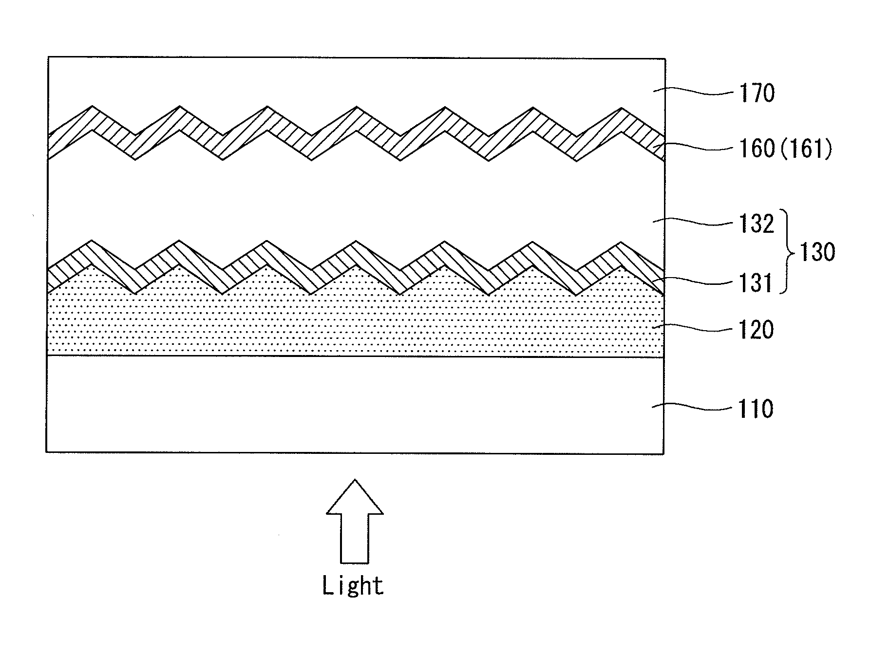
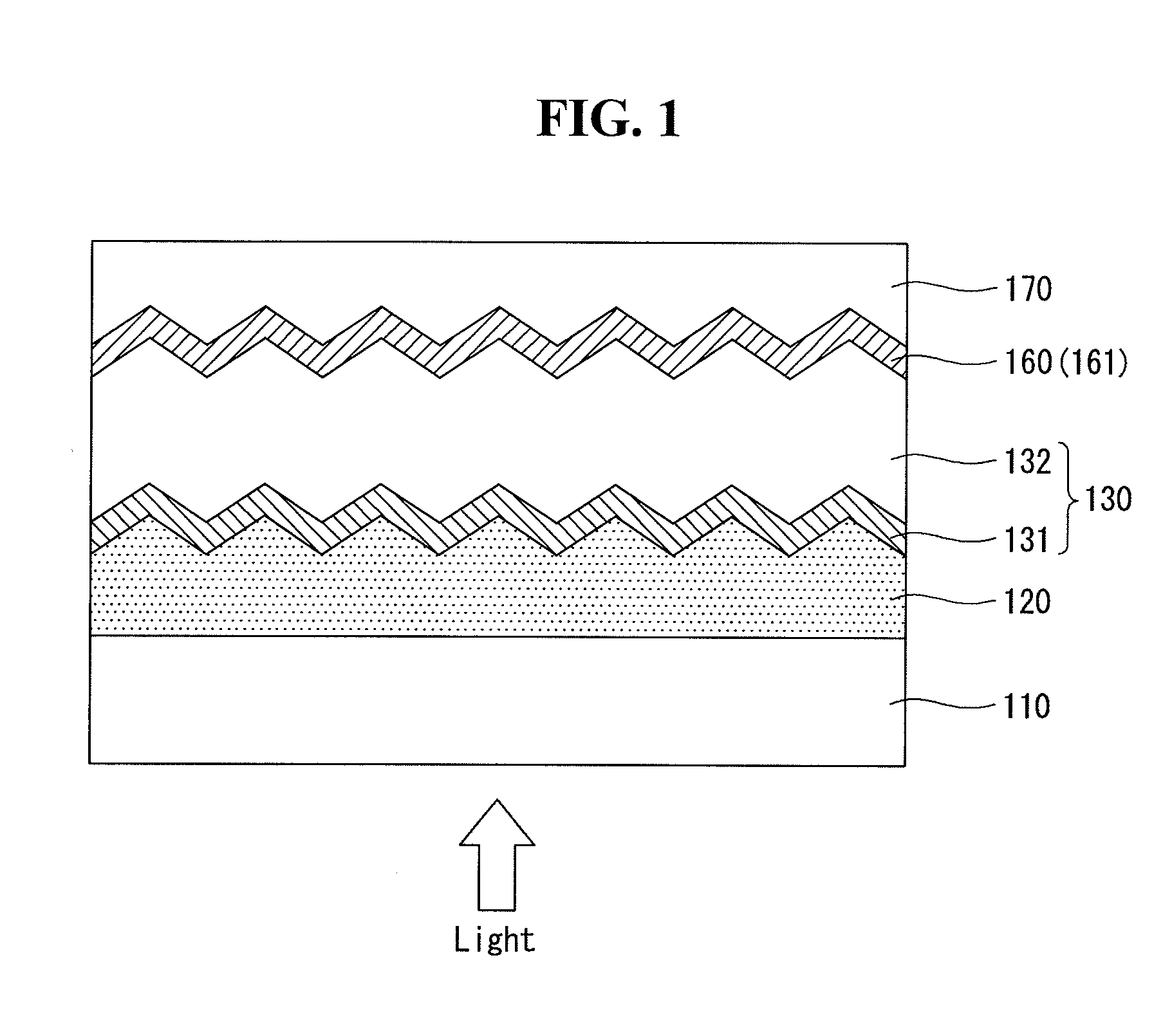
[0030]In the embodiment of the invention using the first back reflection layer of the back reflection layer as a doped layer, the first back reflection layer directly contacts the first intrinsic layer. Therefore, the loss of light is reduced or prevented. As a result, a current reduction of the thin film solar cell is reduced or prevented.
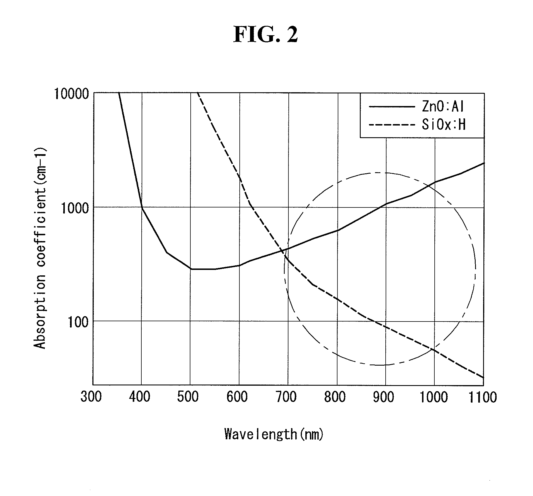
[0031]In the embodiment of the invention, because the first back reflection layer is formed of one of hydrogenated microcrystalline silicon oxide (μc-SiOx:H), hydrogenated microcrystalline silicon nitride (μc-SiNx:H), and hydrogenated microcrystalline silicon oxynitride (μc-SiOxNy:H), a solar light component having a long wavelength reaching the second photoelectric conversion unit or the third photoelectric conversion unit is efficiently reflected. Hence, a current of the second and third photoelectric conversion units may increase.
[0032]

Problems solved by technology

The solar cells have the problem of the high electricity generation cost compared to other energy sources.
However, because a bulk solar cell manufactured based on the single crystal silicon wafer or the polycrystalline silicon wafer now uses a raw material having a thickness of at least 150 μm, the raw material cost, i.e., the silicon co

Method used


Image

  • Thin film solar cell
  • Thin film solar cell
  • Thin film solar cell

Examples


Embodiment Construction

[0044]Embodiments of the invention will be described more fully hereinafter with reference to the accompanying drawings, in which example embodiments of the invention are shown. This invention may, however, be embodied in many different forms and should not be construed as limited to the embodiments set forth herein.

[0045]In the drawings, the thickness of layers, films, panels, regions, etc., are exaggerated for clarity. Like reference numerals designate like elements throughout the specification. It will be understood that when an element such as a layer, film, region, or substrate is referred to as being “on” another element, it can be directly on the other element or intervening elements may also be present. In contrast, when an element is referred to as being “directly on” another element, there are no intervening elements present. Further, it will be understood that when an element such as a layer, film, region, or substrate is referred to as being “entirely” on another element...


PUM


Abstract

A thin film solar cell is discussed. The thin film solar cell includes a substrate, a first photoelectric conversion unit positioned on the substrate, and a back reflection layer for reflecting back light transmitted by the first photoelectric conversion unit to the first photoelectric conversion unit. The first photoelectric conversion unit includes a first intrinsic layer for light absorption. The back reflection layer includes a first back reflection layer doped with n-type or p-type impurities, and the first back reflection layer directly contacts the first intrinsic layer of the first photoelectric conversion unit.

Description

[0001]This application claims priority to and the benefit of Korean Patent Application No. 10-2010-0131821 filed in the Korean Intellectual Property Office on Dec. 21, 2010, the entire contents of which are incorporated herein by reference.BACKGROUND OF THE INVENTION[0002]1. Field of the Invention[0003]Embodiments of the invention relate to a thin film solar cell capable of using a back reflection layer as a doped layer.[0004]2. Description of the Related Art[0005]Solar cells use an essentially infinite energy source, i.e., the sun, scarcely produce pollution materials in an electricity generation process, and has a very long life span equal to or longer than 20 years. Furthermore, the solar cells have been particularly spotlighted because of a large economic ripple effect on solar related industries. Thus, many countries have fostered the solar cells as a next generation industry.[0006]Most of the solar cells have been manufactured based on a single crystal silicon wafer or a polyc...

Claims


Application Information

Patent Timeline
IPC IPC(8): H01L31/0216H01L31/0264H01L31/036H01L31/02H01L31/075
CPCH01L31/075H01L31/076H01L31/056Y02E10/548Y02E10/52
Inventor HWANG, SUNTAELEE, SEUNGYOONCHUNG, JINWONAHN, SEHWON
Owner LG ELECTRONICS INC
Why Eureka
Try Eureka