
Particle Interrogation Devices and Methods

a particle interrogation and particle technology, applied in the direction of optical radiation measurement, particle separator tubes, spectral modifiers, etc., can solve the problems of inability to successfully aspirate particles under the conditions described, inability to sample particles, and inability to achieve the effect of reducing elutriative losses and improving overall sampling efficiency

Inactive Publication Date: 2011-08-04
ENERTECHNIX
View PDF42 Cites 62 Cited by
  • Summary
  • Abstract
  • Description
  • Claims
  • Application Information

AI Technical Summary

Benefits of technology

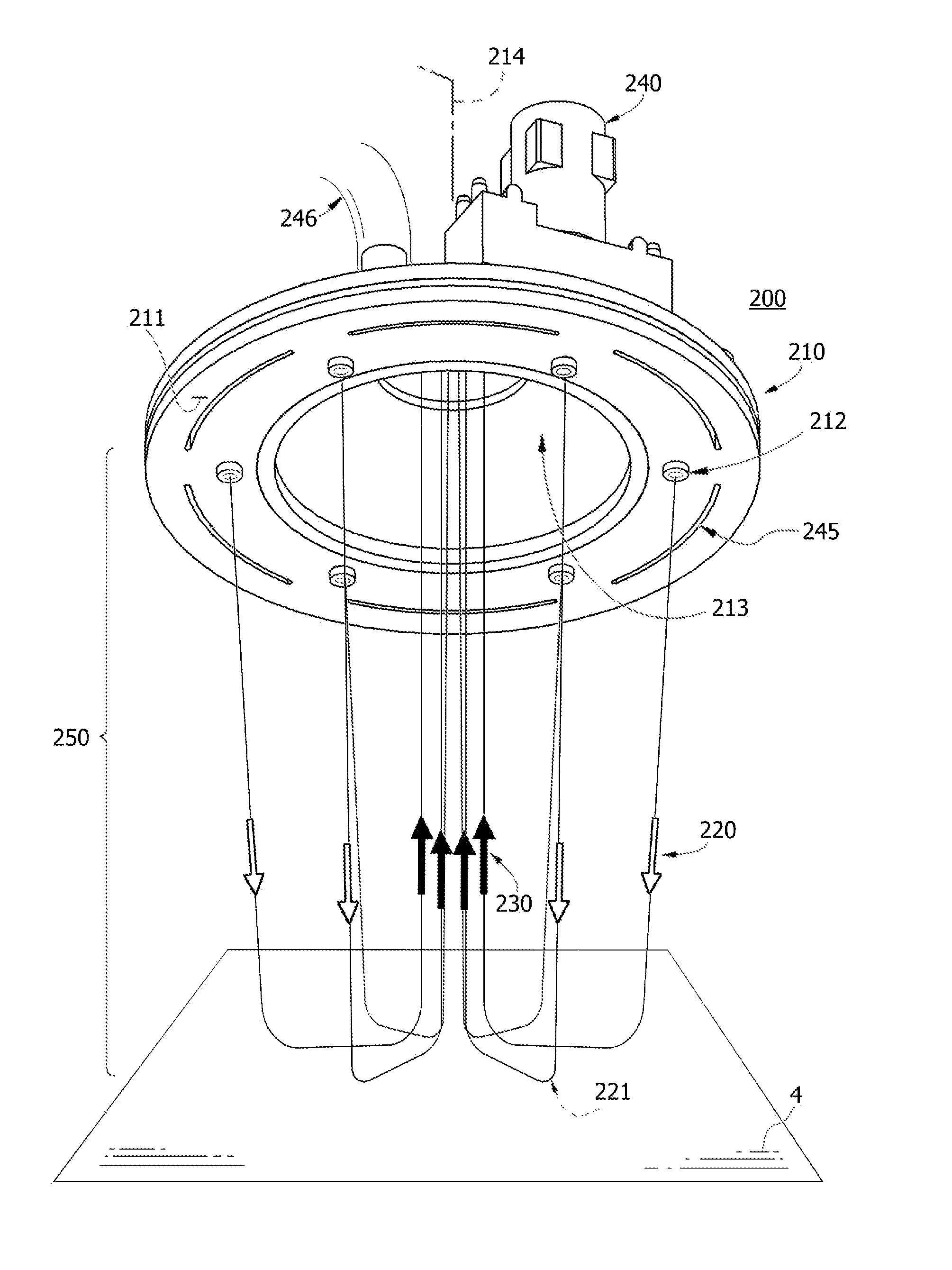
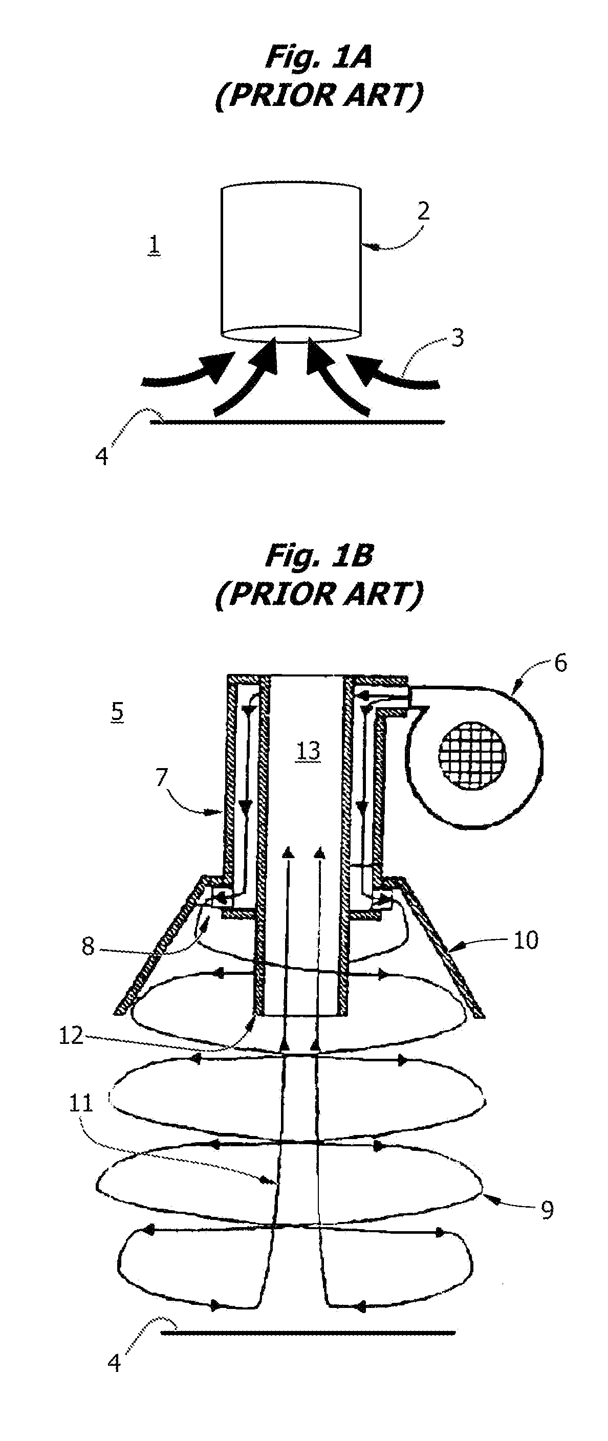
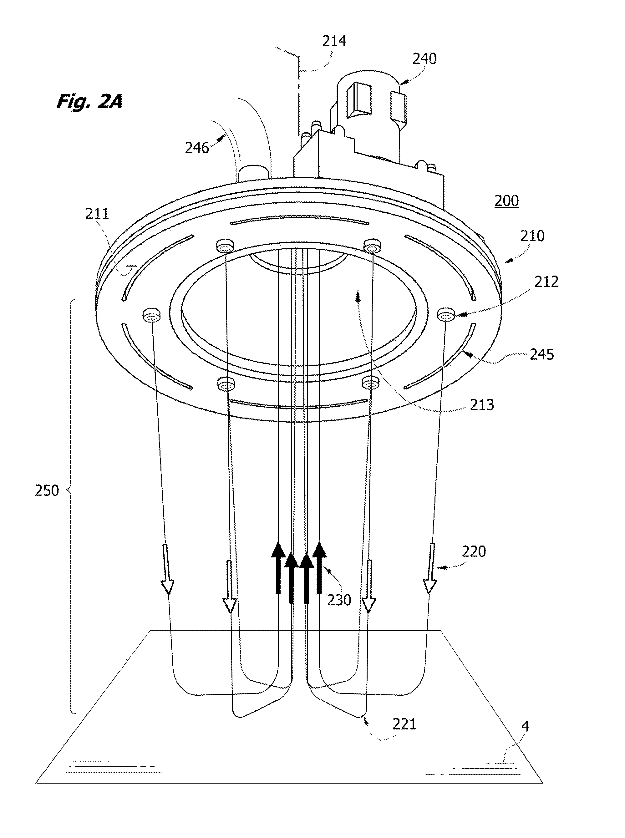
[0026]Surprisingly, we have found that pneumatic pulses or streams emitted from a concentric array of gas interrogation jet nozzles directed in trajectories along the walls of a virtual cone will turn inward when directed at a surface and return to a common suction intake port mounted in the sampler head in the center of the jet array. The sampler head may be held at a distance and aimed at the surface to be interrogated. Targetable jet nozzles and laser guidance may be used to shape the pulse geometry if desired. Particles or vapors removed from the interrogated surface are efficiently mobilized in the “virtual sampling chamber” and aspirated through the suction intake, where they may then be concentrated and analyzed by a variety of methods.
[0031]In yet another aspect, the invention is a method for sampling a residue from an exterior surface of an object, structure or person, which comprises contacting a virtual sampling chamber as described herein with an exterior surface at a distance less than the height Dc of the virtual cone, whereby residues dislodged from the external surface by the gas jets are swept into a sampling return stream by the suction intake. The virtual sampling chamber may be employed intermittently with triggering, or cyclically, or continuously, but is preferentially pulsed with a pulse interval selected so that the jet pulse volume may efficiently be aspirated before firing a second pulse.
[0043]Typically, jets are used to assist in mobilizing, eroding and aerosolizing particles during sampling, as improves the effectiveness of a “particle-only” explosives residue sampling and analysis system.
[0045]Preferably the flow split and the velocity are configured to reduce elutriative losses of particles having an apparent aerodynamic diameter of 5 to 200 microns in the suction intake and wherein the flow split is generally greater than 100:1, the particles being informationally rich. In the systems claimed here, it is envisaged that the bulk flow is discharged to atmosphere without analysis.
[0046]Interchangeable sampler heads may be configured for sampling surfaces and also for interrogating spaces between surfaces, such as under pallets, between stacks of articles, inside vehicle compartments and trash cans, between boxes, in the nap or pile of a rugs, along floorboards, in bins of vegetables, and so forth, where we have found that combinations of jets with suction, can be optimized to improve overall sampling efficiency. Particulates are aerosolized by this treatment and entrained in the suction intake. High velocity jets also erode contaminated substrates to yield additional analyte.

Problems solved by technology

However, the process is inherently slow because each article or person must be moved into the box or chamber and the box sealed before sampling, an obvious disadvantage when large numbers of articles or persons must be screened, or when the articles are larger than can be reasonably enclosed, such as a truck, shipping container, or the hallway surfaces of a building.
However, particles are not sampled and would not be successfully aspirated under the conditions described, which relies on a 250 Watt lamp and a spring-actuated plunger for generating a puff of air.
Various particle and vapor traps are disclosed in patents to Linker of Sandia Labs, including U.S. RE38,797 and U.S. Pat. Nos. 7,299,711, 6,978,657, 6,604,406, 6,523,393, 6,345,545, 6,085,601 and 5,854,431, by Corrigan in U.S. Pat. Nos. 5,465,607 and 4,987,767, and Syage in U.S. Pat. No. 7,299,710, but implementation has proved difficult because particles have been found to poison commonly used vapor trap materials and means for efficiently separating particles and vapors are not recognized.
This has the unfortunate effect of dramatically reducing the amount of analyte available for detection.
One common analytical instrument for detection of nitrate-type explosives relies on pyrolysis followed by redox (electron capture) detection of NO2 groups (Scientrex EVD 3000), but is prone to false alarms.
However, these technologies are associated with aspiration and analysis of vapors, which are typically in vanishingly small concentrations, either because a) the vapor pressure of the material is inherently small, or b) if vapor pressure is larger, then significant quantities of a more volatile analyte will have been lost due to ageing of the material prior to sampling.
Some of these detectors also have had maintenance issues, often related to fouling due to aspiration of particles.
The downstream analyzer can be badly damaged by the entry of intact particles.
Moreover, the particle-by-particle approach taught in the art substantially limits application for high throughput analysis and is not scaleable except by an impractical redundancy of parallel systems.
However, these devices are readily overloaded when confronted with large amounts of complex mixtures, interferents, and dust, such as are likely to be encountered in routine use.
High velocity jets also erode contaminated substrates to yield additional analyte.

Method used


Image

  • Particle Interrogation Devices and Methods
  • Particle Interrogation Devices and Methods
  • Particle Interrogation Devices and Methods

Examples


example

[0249]In one study, 20 nanograms of TNT trace explosive was deposited on a glass surface using a dry transfer technique from a Teflon® Bytek strip and interrogated with a surface sampler of the invention. The dry transfer technique was performed essentially as described by Chamberlain (U.S. Pat. No. 6,470,730). Particle size distribution (crystal size distribution) was about 10-200 microns. The apparatus was operated with a 3 mm jet array at 80 psig back pressure. The dislodged TNT particles were aspirated at a 1000 sLpm flow rate into a high flow air-to-air particle concentrator with aerodynamic lenses and skimmer and captured in a particle trap formed of a 13 mm pervious member. Explosives constituents of captive particles were dissolved by injection of 100 μL of acetonitrile, of which 10 μL was injected into an IMS detector. A measurable TNT signal was observed. The experiment demonstrates detection of trace explosive residues at a nanogram detection level using a jet-assisted no...


PUM


Abstract

Devices, apparatus and methods are disclosed for non-contact pneumatic sampling and sampling of surfaces, persons, articles of clothing, buildings, furnishings, vehicles, baggage, packages, mail, and the like, for contaminating aerosols indicative of a hazard or a benefit, where the contaminating aerosols are chemical, radiological, biological, toxic, or infectious in character. In a first device, a central orifice for pulling a suction gas stream is surrounded by a peripheral array of convergingly-directed gas jets, forming a virtual sampling chamber. The gas jets are configured to deliver millisecond pneumatic pulses that erode particles from solid surfaces at a distance. In another aspect of the invention, a suction gas stream is split using an air-to-air concentrator so that a particle-enriched gas flow is directed to a particle trap and any particles immobilized in the particle trap (including any adsorbed vapors associated with the particles) are selectively analyzed to detect trace residues associated with explosives.

Description

CROSS-REFERENCE TO RELATED APPLICATIONS[0001]This application is a continuation-in-part of U.S. patent application Ser. No. 12 / 834,860, filed 12 Jul. 2010, which claims the benefit of priority under 35 U.S.C. §119(e) from U.S. Provisional Patent Application No. 61 / 318,313 filed Mar. 27, 2010 and from U.S. Provisional Patent Application No. 61 / 225,007 filed Jul. 13, 2009; said patent documents being incorporated herein in entirety for all purposes by reference.GOVERNMENT SUPPORT[0002]The United States Government may have certain rights in this invention pursuant to Grant Nos. HSHQDC-08-C-00076 and HSHQDC-09-C-00131 awarded by the Department of Homeland Security.FIELD AND BACKGROUND OF THE INVENTION[0003]The invention relates to sampling and concentrative apparatus and methods for collection of trace analytes from surfaces and substrates where the analyte is in the form of a particulate or a vapor adherent to a particulate and particularly to such apparatus and methods as are useful i...

Claims


Application Information

Patent Timeline
IPC IPC(8): G01N1/28H01J49/26H01J27/00B01D15/08G01N30/00G01J3/00G01J1/58G01N27/62G01N27/447G01N33/00
CPCB01D15/08G01J1/58G01J3/00G01N27/447H01J49/26G01N1/28G01N30/00G01N33/00H01J27/00G01N27/62Y02A50/20
Inventor NOVOSSELOV, IGOR V.ARIESSOHN, PETER C.DENGLER, EVAN D.HICKNER, MICHELLE
Owner ENERTECHNIX
Learn More