Robust mixed conducting membrane structure

a mixed conducting membrane and membrane structure technology, applied in the field of membranes, can solve the problems of not posing sufficient thermodynamic stability for operating at low posub>2, and achieve the effect of limiting the performance of the mixed conducting membrane in general by either, stressing the other parts of the apparatus containing the membran

Inactive Publication Date: 2011-08-04
DANMARKS TEKNISKE UNIV
View PDF8 Cites 2 Cited by
  • Summary
  • Abstract
  • Description
  • Claims
  • Application Information

AI Technical Summary

Problems solved by technology

However, they do not posses sufficient thermodynamic stability for operating at low pO2, as is required for instance for production of synthesis gas in a membrane reactor.
The performance of a mixed conducting membrane will in general be limited by either the electronic or the ionic conductivity, whichever is lower.
Also the thermal expansion of the membrane at high

Method used


Image

  • Robust mixed conducting membrane structure
  • Robust mixed conducting membrane structure
  • Robust mixed conducting membrane structure

Examples


example 1

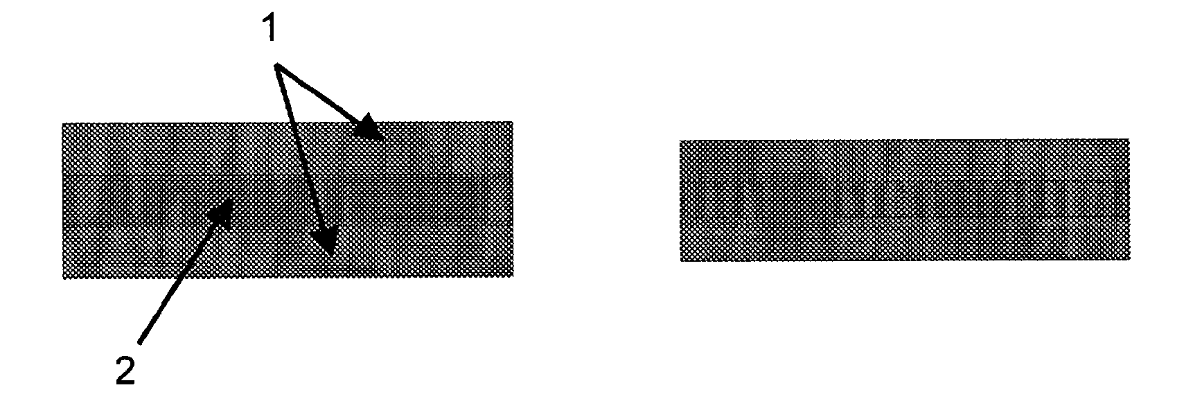
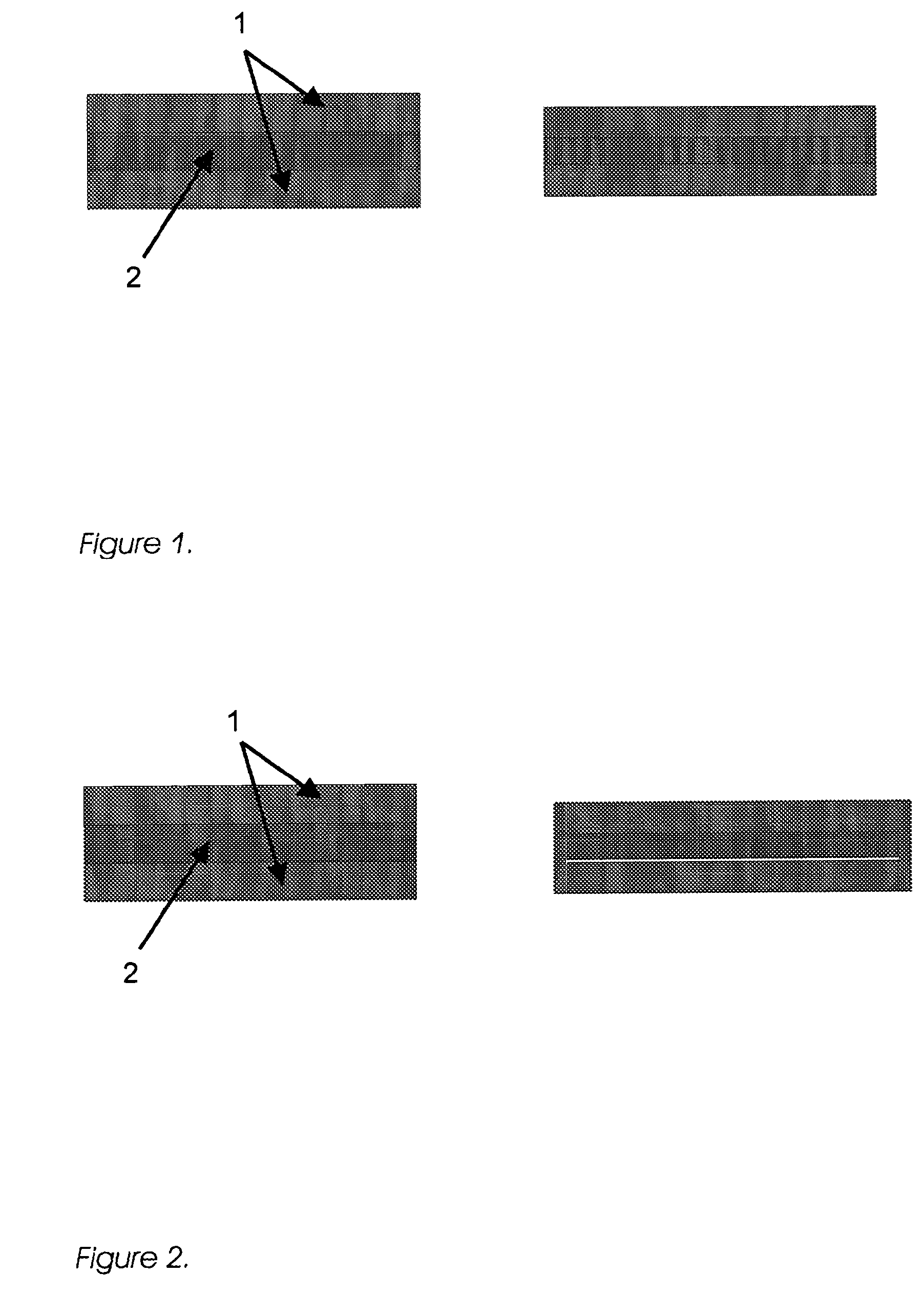
[0060]A symmetric flat plate membrane structure as illustrated in FIG. 1 is obtained.

[0061]The first step was the tape-casting of a metal containing layer and a membrane layer.

[0062]Suspensions for tape-casting were manufactured by means of ball milling of powders with polyvinyl pyrrolidone (PVP), polyvinyl butyral (PVB) and EtOH+MEK as additives. After control of the particle size, the suspensions were tape-cast using a double doctor blade system and the tapes are subsequently dried.

[0063]Layer 1 (metal containing layer): The suspension comprised Fe22Cr. The green thickness was in the range of 50 to 70 μm. The sintered porosity of the layer was about 50% with a pore size in the range of 1 to 2 μm.

[0064]Layer 2 (membrane layer): The suspension comprised Ce0.9Gd0.1O2-δ (CGO10) powder. The green thickness of the foil was around 25 μm. The sintered density of the layer was >96% of theoretical density.

[0065]The second step was the lamination of the above mentioned foils into symmetrical...

example 2

[0070]A symmetric flat plate membrane structure as illustrated in FIG. 1 was obtained.

[0071]The first step was the tape-casting of a metal containing layer and a membrane layer.

[0072]Suspensions for tape-casting were manufactured by means of ball milling of powders with polyvinyl pyrrolidone (PVP), polyvinyl butyral (PVB) and EtOH+MEK as additives.

[0073]After control of the particle size, the suspensions were tape-cast using a double doctor blade system and the tapes are subsequently dried.

[0074]Layer 1 (metal containing layer): The suspension comprised Fe22Cr. The green thickness was in the range of about 50 to 70 μm. The sintered porosity of the layer was about 50% with a pore size in the range of 1 to 2 μm.

[0075]Layer 2 (membrane layer): The suspension comprised Ce0.9Gd0.1O2-δ (CGO10) powder and 20 vol % Fe22Cr. The green thickness of the foil was around 25 μm. The sintered density of the layer was >96% of theoretical density.

[0076]The membrane was completed as described in Examp...

example 3

[0077]A symmetric flat plate membrane structure as illustrated in FIG. 1 was obtained.

[0078]The first step was the tape-casting of a metal containing layer and a membrane layer.

[0079]Suspensions for tape-casting were manufactured by means of ball milling of powders with polyvinyl pyrrolidone (PVP), polyvinyl butyral (PVB) and EtOH+MEK as additives. After control of the particle size, the suspensions were tape-cast using a double doctor blade system and the tapes are subsequently dried.

[0080]Layer 1 (metal containing layer): The suspension comprised Fe22Cr. The green thickness was in the range of about 50 to 70 μm. The sintered porosity of the layer was about 50% with a pore size in the range of 1 to 2 μm.

[0081]Layer 2 (membrane layer): The suspension comprised Ce0.9Gd0.1O2-δ (CGO10) powder and 30 vol % (La0.88Sr0.12)s(Cr0.92V0.14)O3-δ. The green thickness of the foil was around 25 μm. The sintered density of the layer was >96% of theoretical density.

[0082]The membrane was completed ...


PUM


Abstract

The present invention provides a membrane, comprising in said order a first electronically conducting layer, an ionically conducting layer, and a second electronically conducting layer,
characterized in that the first and second electronically conducting layers are internally short circuited.
The present invention further provides a method of producing the above membrane, comprising the steps of:
    • providing a ionically conducting layer;
    • applying at least one layer of electronically conducting material on each side of said ionically conducting layer;
    • sintering the multilayer structure; and
    • impregnating the electronically conducting layers with a catalyst material or catalyst precursor material.

Description

FIELD OF THE INVENTION[0001]The present invention relates to a membrane which comprises a first electronically conducting layer, an ionically conducting layer, and a second electronically conducting layer, wherein the electronically conducting layers are internally short circuited, and a method of producing same.BACKGROUND OF THE INVENTION[0002]Generally, separation membranes are made from various inorganic or organic materials, including ceramics, metals and polymers. For example, ceramic structures are oxygen ion conductors and are suitable to cause selective permeation of oxygen ions at high temperatures, such as about 500° C. or higher. Membranes comprising at least a layer of said ceramic materials are therefore suitable to separate oxygen from oxygen containing gas mixtures.[0003]More specifically, it has been suggested to apply electrodes to both sides of a ceramic membrane structure and to connect said electrodes externally. On one side of the membrane, the oxygen partial pr...

Claims


Application Information

Patent Timeline
IPC IPC(8): B01D53/46B05D5/12B01J19/00
CPCB01D53/228B01D67/0046B01D67/0088B01D69/141C01B13/0255B01D2256/12B01D2256/16B01D2325/10C01B3/503B01D71/025
Inventor LINDEROTH, SORENLARSEN, PETER HALVOR
Owner DANMARKS TEKNISKE UNIV
Why Eureka
Try Eureka