Micro-channel-cooled high heat load light emitting device

a light-emitting device and microchannel cooling technology, applied in semiconductor devices, lighting and heating apparatus, lighting sources, etc., can solve the problems of large waste heat production, and low efficiency of led devices of today's uv leds, and achieve high fill factor, thermally efficient electrical connection, and high aspect ratio

Inactive Publication Date: 2011-08-25
HERAEUS NOBLELIGHT AMERICA
View PDF41 Cites 37 Cited by
  • Summary
  • Abstract
  • Description
  • Claims
  • Application Information

AI Technical Summary

Benefits of technology

[0011]Micro-channel-cooled UV curing systems and components thereof are described that are configured for photo-chemical curing of materials and other high-brightness/high-irradiance applications. According to one embodiment, a lamp head module includes an optical macro-reflector, an array of light emitting diodes (LEDs) and a micro-channel cooler assembly. The optical macro-reflector includes a window having an outer surface. The array is positioned within the optical reflector and has a high fill factor and a high aspect ratio. The array is operable to provide a high irradiance output beam pat

Problems solved by technology

Today's UV LEDs remain relatively inefficient (typically, operating at about 15% efficiency when operated at high current densities).
These inefficiencies result in the production of large quantities of waste heat and therefore requiring at least air cooling and often liquid cooling (e.g., heat exchangers and/or chillers) to remove the unwanted waste heat, which is a by-product of the electrical to optical conversion process within the p-n junction of the semiconductor device.
If the heat is not removed in a very effective and efficient manner, the LED devices may suffer loss of efficiency, decrease in light output and even catastrophic failure.
Liquid-cooled UV LED lamps (or light engines) are currently being used in a variety of curing applications; however, existing systems have several limitations.
One drawback to this series-parallel methodology is that the heat sinks usually have to be of a non-electrically conductive nature and/or there needs to be a dielectric layer underneath the LED(s), either of which is traditionally patterned with electrically conductive circuit traces.
These traces are expensive and incompatible with thermally efficient ultra-high current operation because of the contact thermal resistance of the layers involved and/or the bulk thermal resistance of the dielectric layer and/or the inherently high electrical resistivity of traces.
The heat sinks are also oft

Method used


Image

  • Micro-channel-cooled high heat load light emitting device
  • Micro-channel-cooled high heat load light emitting device
  • Micro-channel-cooled high heat load light emitting device

Examples


Embodiment Construction

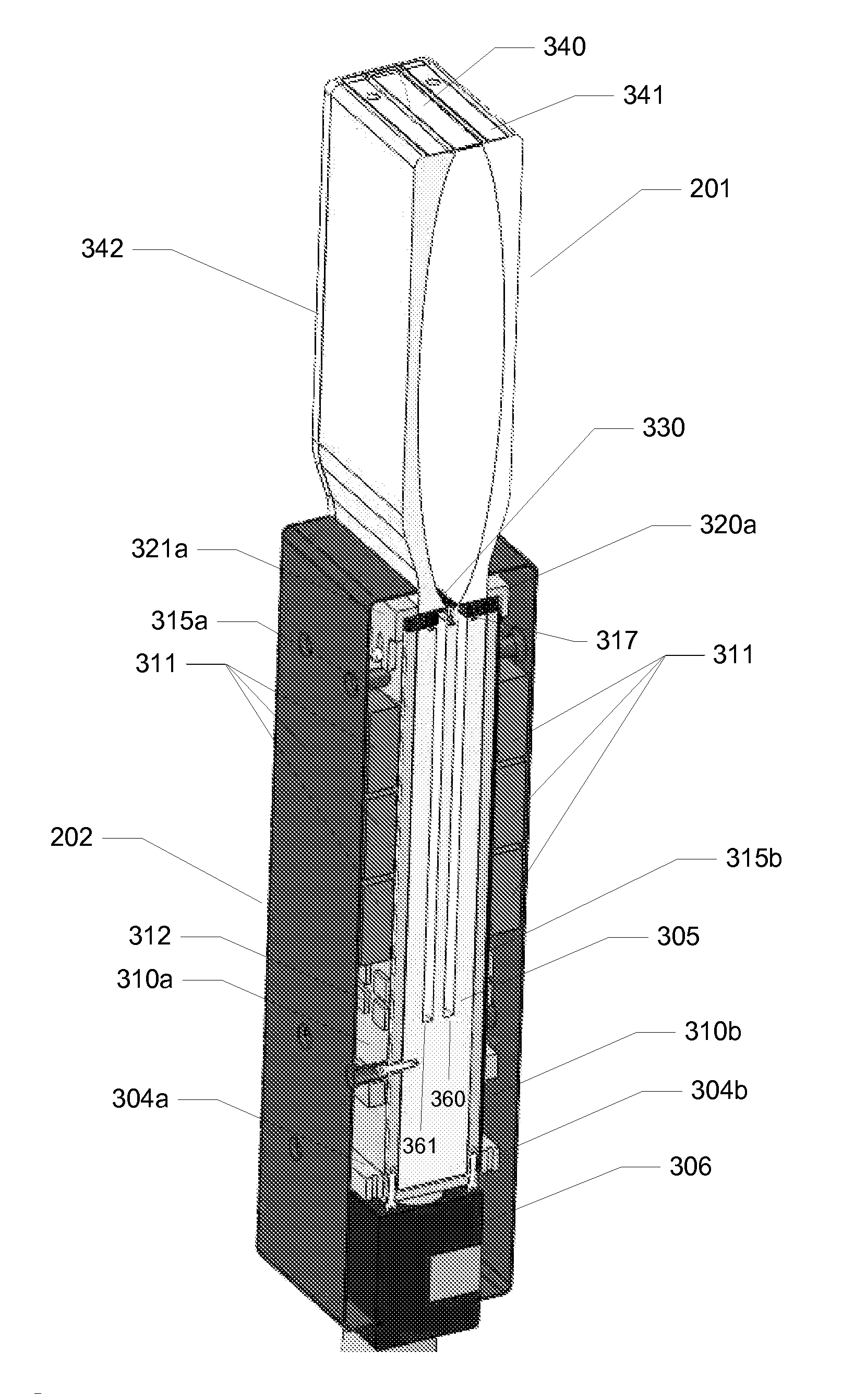
[0060]Micro-channel-cooled UV curing systems and components thereof are described that are configured for photo-chemical curing of materials and other applications requiring high fill-factor, high current density and high-brightness attributes (which ultimately leads to the attribute of high-irradiance). According to one embodiment of the present invention, LEDs of a high fill factor LED array of an ultra high irradiance UV curing system are placed substantially in electrical parallel (a / k / a massively parallel) on a common anode substrate to achieve a very thermally efficient manner of connection (e.g., with no thermally impeding dielectric layer between the base of the LEDs and the substrate as is typically required in a series configuration or a series / parallel configuration).

[0061]According to embodiments of the present invention, in order to accommodate the heat flux / thermal demands of a high fill-factor, high current density and high-brightness UV LED lamp head module, practica...


PUM


Abstract

Micro-channel-cooled UV curing systems and components thereof are provided. According to one embodiment, a lamp head module includes an optical macro-reflector, an array of LEDs and a micro-channel cooler assembly. The array is positioned within the reflector and has a high fill factor and a high aspect ratio. The array provides a high irradiance output beam pattern having a peak irradiance of greater than 25 W/cm2 at a work piece surface at least 1 mm away from an outer surface of a window of the reflector. The micro-channel cooler assembly maintains a substantially isothermal state among p-n junctions of the LEDs at less than or equal to 80° Celsius. The micro-channel cooler assembly also provides a common anode substrate for the array. A thermally efficient electrical connection is formed between the array and the common anode substrate by mounting the array to the micro-channel cooler assembly.

Description

CROSS-REFERENCE TO RELATED APPLICATIONS[0001]This application claims the benefit of priority to U.S. Provisional Patent Application No. 61 / 336,979, filed on Jan. 27, 2010; U.S. Provisional Patent Application No. 61 / 341,594, filed on Apr. 1, 2010; and U.S. Provisional Patent Application No. 61 / 456,426, filed on Nov. 5, 2010, all of which are hereby incorporated by reference in their entirety for all purposes.COPYRIGHT NOTICE[0002]Contained herein is material that is subject to copyright protection. The copyright owner has no objection to the facsimile reproduction of the patent disclosure by any person as it appears in the Patent and Trademark Office patent files or records, but otherwise reserves all rights to the copyright whatsoever. Copyright© 2010-2011, Fusion UV Systems, Inc.BACKGROUND[0003]1. Field[0004]Embodiments of the present invention generally relate to light emitting diodes (LEDs) on low thermal resistance substrates. In particular, embodiments of the present invention ...

Claims


Application Information

Patent Timeline
IPC IPC(8): G21K5/00
CPCF21K9/30F21V29/30F21K9/20F21Y2101/00B05D3/067H01L2224/48091H01L2224/48465H01L2224/45144H01L2924/00014H01L2924/00F21V29/56
Inventor DAHM, JONATHAN S.JONGEWAARD, MARKCAMPBELL, GEOFF
Owner HERAEUS NOBLELIGHT AMERICA
Why Eureka
Try Eureka