
Semiconductor device and method of manufacturing the same

a technology of semiconductor devices and semiconductor devices, which is applied in the direction of semiconductor devices, semiconductor/solid-state device details, electrical apparatus, etc., can solve the problems of reducing the yield, reducing the connection reliability, and reducing the product quality of semiconductor devices, so as to improve the yield of products, improve the connection reliability, and high barrier properties

Active Publication Date: 2011-08-25
ULVAC INC +1
View PDF9 Cites 5 Cited by
  • Summary
  • Abstract
  • Description
  • Claims
  • Application Information

AI Technical Summary

Benefits of technology

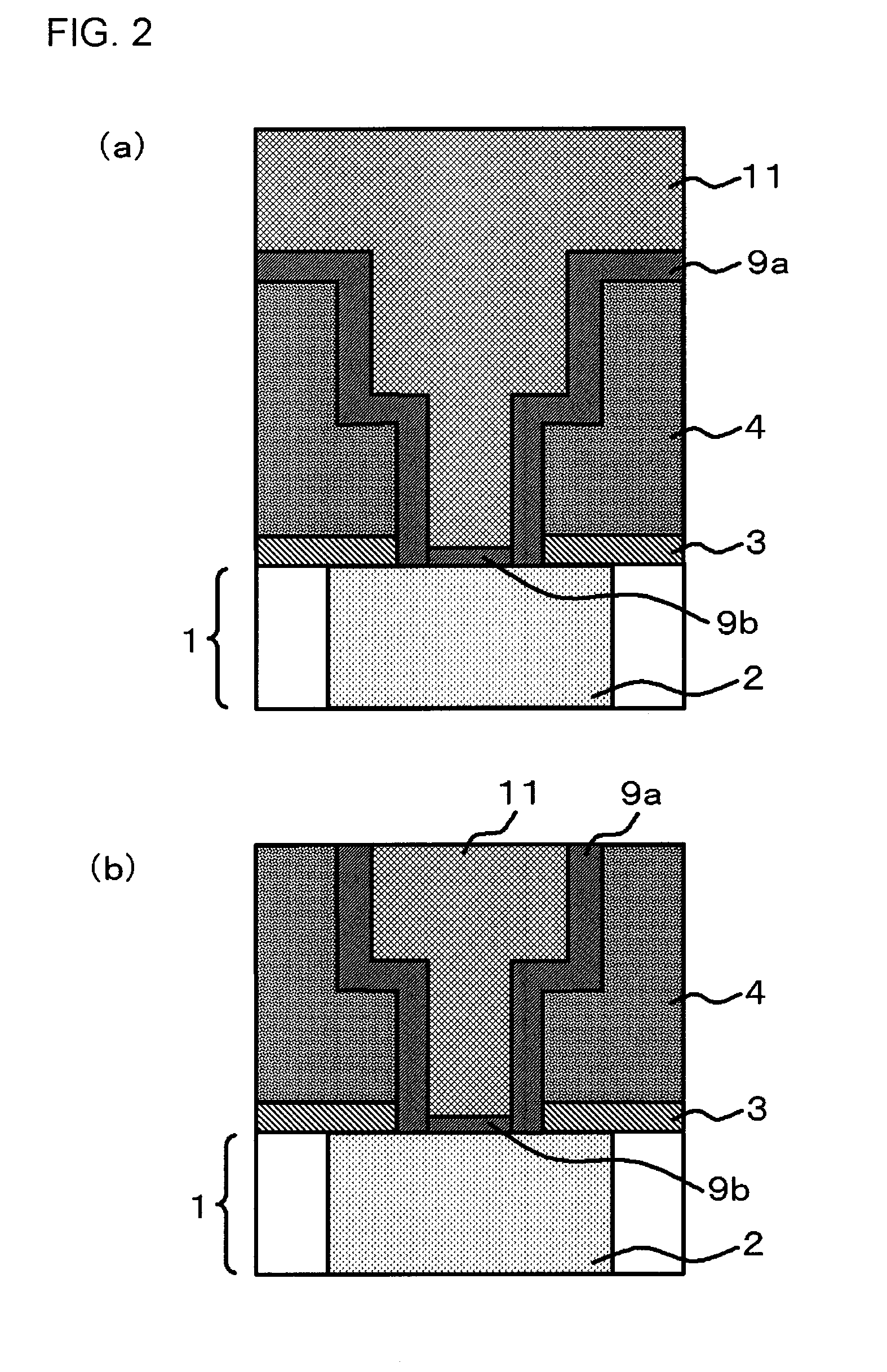
[0020]According to this invention, since the semiconductor device has a carbon-containing metal film that isolates between the porous dielectric layer and the second interconnect, diffusion of the metal is suppressed. For this reason, generation of electromigration, stress migration, or the like is suppressed, whereby the connection reliability is improved. Therefore, a semiconductor device having an interconnect of high quality with a long operation-ensuring lifetime can be provided.
[0021]Further, since the semiconductor device does not have an insulative film between the first interconnect and the second interconnect, the contact resistance between the first interconnect and the second interconnect electrically connected thereto become small, so that a high-performance interconnect with a low interconnect resistance is formed. For this reason, the product quality of the semiconductor device is improved, and the yield also is improved.
[0023]According to this invention, by introducing the carbon contained in the reactive carbon-containing compound into the metal film on the porous dielectric layer surface, a carbon-containing metal film can be formed selectively on the porous dielectric layer surface and, furthermore, an insulating film is not formed on the first interconnect surface. In this manner, by a convenient method, it is possible to cover only the porous dielectric layer surface within the interconnect trench efficiently with a carbon-containing metal film having a high barrier property, whereby a semiconductor device being excellent in connection reliability and product quality with improved yield of the product can be obtained.
[0024]The semiconductor device according to the present invention is excellent in the connection reliability between the interconnects, so that the product quality is excellent and the yield is improved. Further, according to the method of manufacturing a semiconductor device according to the present invention, such a semiconductor device can be obtained efficiently by a convenient method.

Problems solved by technology

In other words, in the semiconductor device disclosed in Patent Document 1, the resistance between the interconnects has sometimes increased, thereby leading to decrease in the connection reliability.
For this reason, decrease in the product quality of the semiconductor device and decrease in the yield have been provoked.
For this reason, even if the semiconductor device has a barrier metal film, diffusion of Cu into the porous film is not sufficiently suppressed, whereby electromigration, stress migration, or the like may sometimes occur, leading to decrease in the connection reliability.

Method used

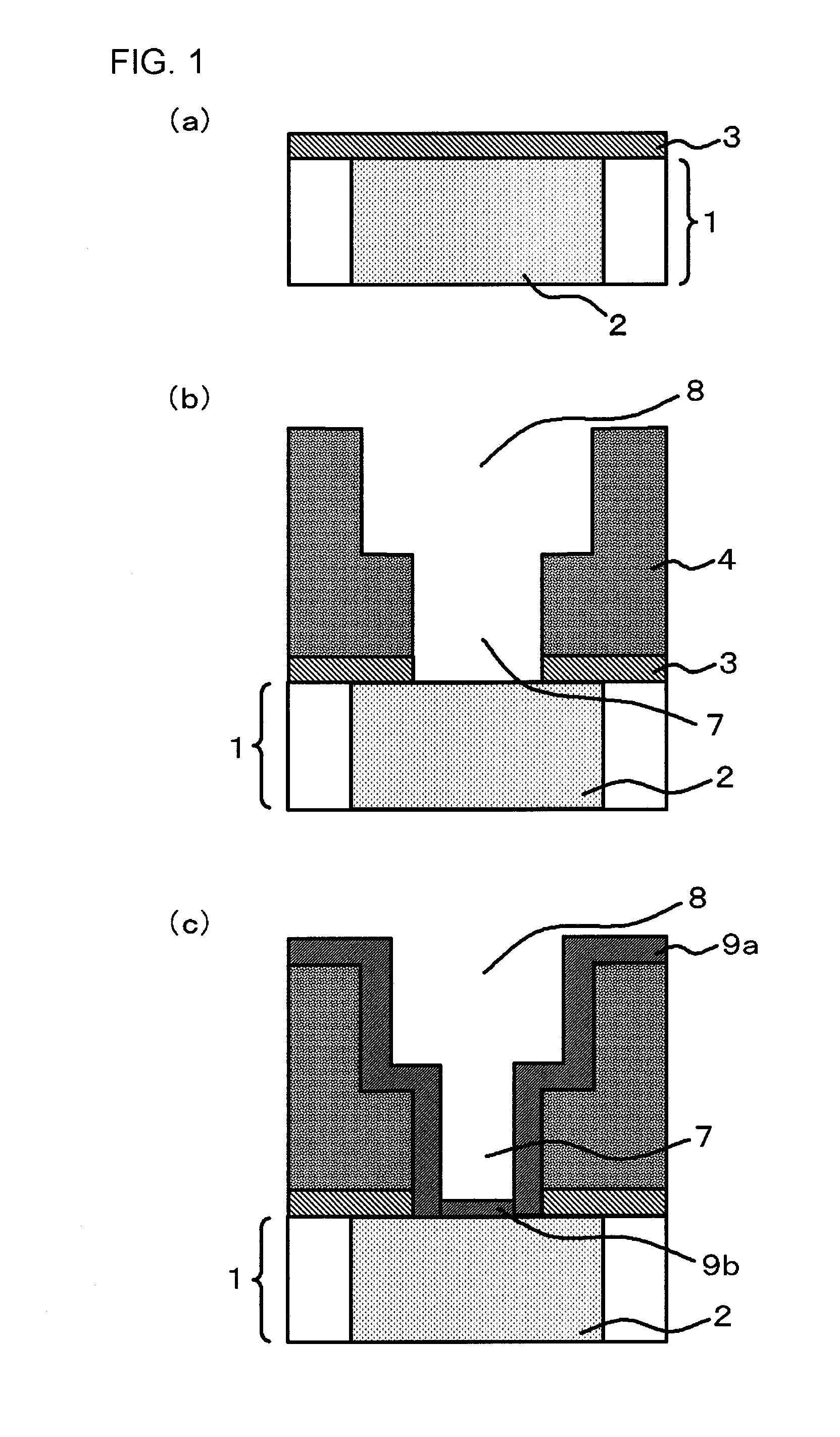

Image

  • Semiconductor device and method of manufacturing the same
  • Semiconductor device and method of manufacturing the same
  • Semiconductor device and method of manufacturing the same

Examples


first embodiment

[0034]Referring to FIG. 2(b), a semiconductor device of the present embodiment includes a first interconnect 2, a porous dielectric layer 4 formed on the first interconnect 2, a second interconnect 11 buried in the porous dielectric layer 4 and electrically connected to the first interconnect 2, and a carbon-containing metal film 9a that is disposed between the porous dielectric layer 4 and the second interconnect 11 and isolates these layers. A metal film 9b is provided between the first interconnect 2 and the second interconnect 11. Over an underlayer film 1 including the first interconnect 2, an etching-stop diffusion-barrier film 3 is provided between the underlayer film 1 and the porous dielectric layer 4.

[0035]The first interconnect 2 and the second interconnect 11 are formed of an interconnect material having a low resistance, and the material thereof is made, for example, of Cu, Al or an alloy containing these as major components. The etching-stop diffusion-barrier film 3 is...

second embodiment

[0075]Referring to FIG. 4(b), a semiconductor device of the present embodiment includes a first interconnect 2, a porous dielectric layer 4 formed on the first interconnect 2, and a second interconnect 11 buried in the porous dielectric layer 4 and electrically connected to the first interconnect 2. Further, between the porous dielectric layer 4 and the second interconnect 11, a carbon-containing metal film 9a and a barrier metal film 10 are provided in the order from the porous dielectric layer 4. A metal film 9b is provided between the first interconnect 2 and the barrier metal film 10.

[0076]The carbon-containing metal film 9a contains carbonized metal similar to that in the first embodiment. Here, in the present embodiment, the film thickness of the carbon-containing metal film 9a is 3 nm or more and 50 nm or less. In the present embodiment, description is given by an example using a carbon-containing metal film 9a having a film thickness of about 25 nm.

[0077]In the present embod...


PUM

PropertyMeasurementUnit
thicknessaaaaaaaaaa
thicknessaaaaaaaaaa
pressureaaaaaaaaaa

Abstract

A semiconductor device includes a first interconnect, a porous dielectric layer formed over the first interconnect, a second interconnect buried in the porous dielectric layer and electrically connected to the first interconnect, and a carbon-containing metal film that is disposed between the porous dielectric layer and the second interconnect and isolates these layers.

Description

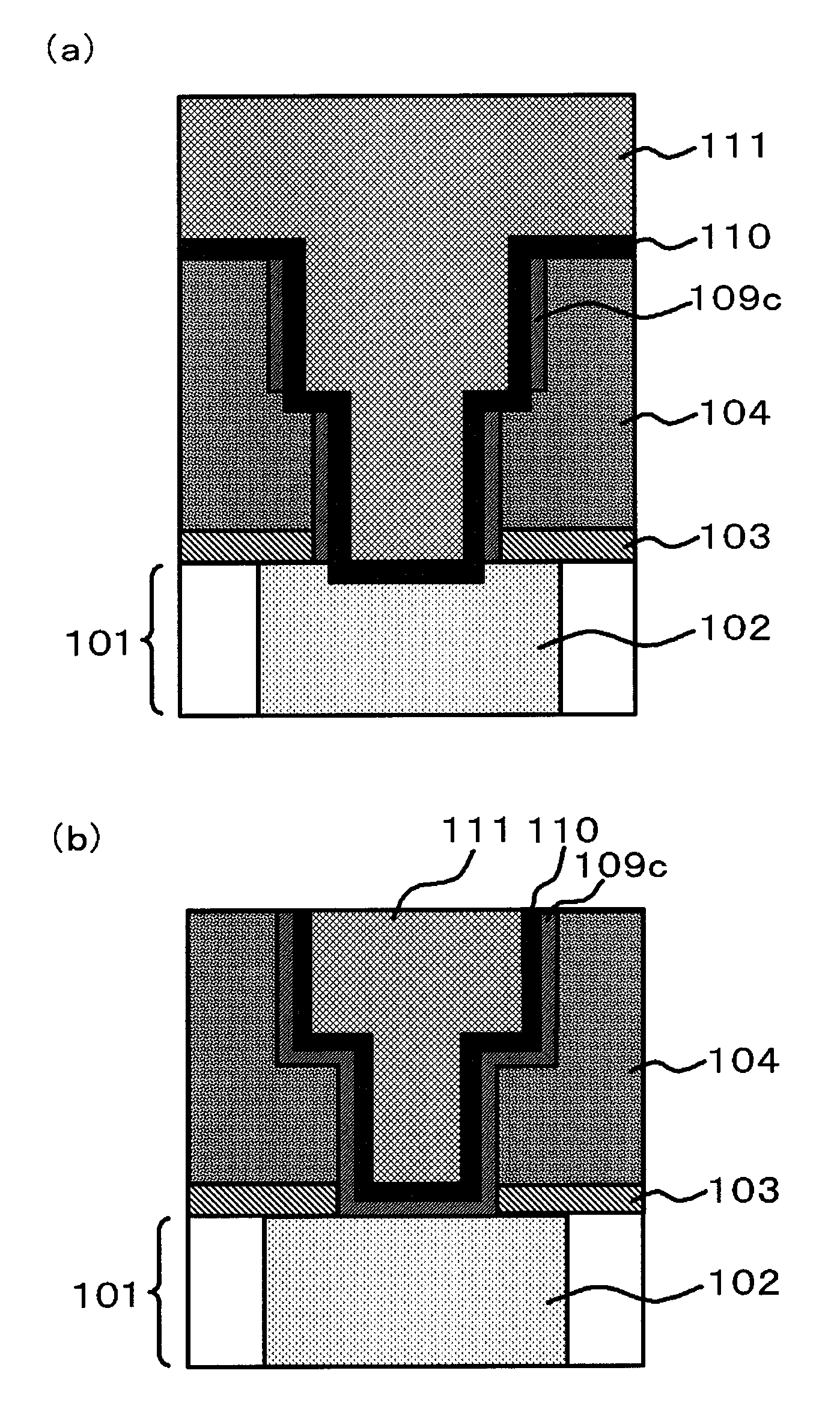
TECHNICAL FIELD[0001]The present invention relates to a semiconductor device provided with a porous dielectric layer and a method of manufacturing the same.BACKGROUND ART[0002]Patent Document 1 discloses a method of improving the covering completeness of a barrier film by attaching a polymer film onto a porous dielectric film surface by a hydrocarbon plasma treatment.[0003]In the method disclosed in Patent Document 1, first, as shown in FIG. 5(a), an etching-stop diffusion-barrier film 103 is formed on an underlayer film 101 having an interconnect 102 on a semiconductor substrate. The etching-stop diffusion-barrier film is typically a silicon nitride film (Si3N4) or a silicon carbide film (SiC). Then, a porous dielectric layer 104 having a low dielectric constant is formed. Thereafter, a via 107 and a trench 108 are formed by etching with use of a photoresist mask. After the mask is removed by asking, the via penetrates through the porous dielectric layer 104 and the etching-stop di...

Claims


Application Information

Patent Timeline
Patent Type & Authority Applications(United States)
IPC IPC(8): H01L23/532H01L21/768
CPCH01L21/02337H01L21/02359H01L21/3105H01L21/7682H01L21/76825H01L21/76831H01L21/76843H01L2924/0002H01L21/76846H01L23/53223H01L23/53238H01L23/53295H01L2924/00H01L21/76814H01L21/76826
Inventor CHIKAKI, SHINICHINAKAYAMA, TAKAHIRO
Owner ULVAC INC
Learn More