Method and apparatus to measure particle mobility in solution

a technology of particle mobility and solution, applied in the direction of fluid pressure measurement, liquid/fluent solid measurement, peptides, etc., can solve the problems of reducing the measurement time associated with mp-pals and reducing so as to reduce the damage to fragile biological samples, improve the accuracy of mobility determination, and reduce the effect of measurement tim

Active Publication Date: 2011-09-01
WYATT TECH
View PDF6 Cites 34 Cited by
  • Summary
  • Abstract
  • Description
  • Claims
  • Application Information

AI Technical Summary

Benefits of technology

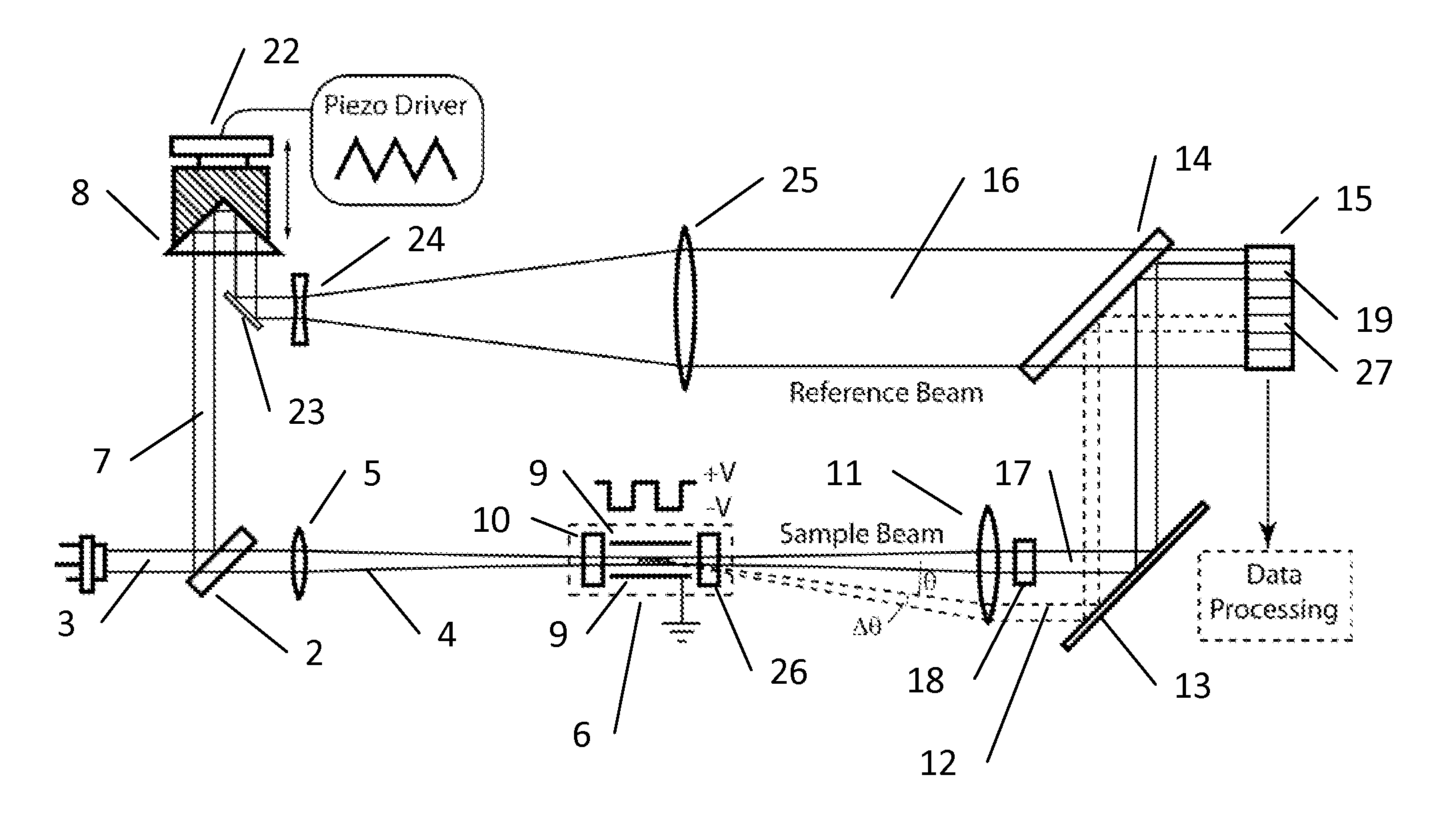
[0009]This innovative implementation of the PALS technique begins conventionally with a coherent beam of laser light being split to produce two beams, a reference beam and a sample beam. The reference beam is directed to a modulator that impresses upon it a time varying phase modulation. This beam is then expanded and shaped so that it fully illuminates a detector array. The sample beam is focused into and passes through a cell containing a fluid sample comprising a suspension of molecules whose mobility is to be measured. Electrodes within the cell apply a time varying electric field to the illuminated sample. The transmitted sample beam, along with a portion of the light scattered by the sample, which now contains information about the motion of the molecules, are collimated by a lens. This sample beam is combined with the reference beam to form an interference speckle pattern on the detector array. The array is chosen so that each element covers one or more coherence areas of the speckle pattern and covers a narrow range of scattering angles determined by the focal length of the collimating lens. Since the reference beam is phase modulated, each detector element records a time varying signal with a frequency set by the phase modulator. The electronic signal from each detector element is amplified and filtered by a band pass filter around this frequency. One element on the array, the forward monitor, detects interference of the unscattered sample beam and the reference beam. The forward monitor measures the exact phase modulation that was impressed upon the reference beam. This signal is then used to demodulate the signals corresponding to the different scattering angles. The phase difference between the forward monitor and each detector determines the accumulated optical phase, and thereby, the mobility of the sample. The most important benefit conferred by this measurement technique is that each detector element provides an independent, simultaneous measurement. Since the precision of the mobility determination improves with the number of detectors used, an array with a large number of elements is preferred. Therefore, the technique is referred to as massively parallel phase analysis light scattering, MP-PALS. By averaging a number of elements the time required to achieve a specified precision decreases inversely as the number of elements, enabling the measurement of very small particles such as proteins. In addition, the reduced measurement time associated with MP-PALS decreases damage to fragile biological samples while minimizing electrochemical degradation of the electrodes.

Problems solved by technology

In addition, the reduced measurement time associated with MP-PALS decreases damage to fragile biological samples while minimizing electrochemical degradation of the electrodes.

Method used


Image

  • Method and apparatus to measure particle mobility in solution
  • Method and apparatus to measure particle mobility in solution
  • Method and apparatus to measure particle mobility in solution

Examples


Embodiment Construction

.

[0007]Because the combined beam intensity ratios of the traditional PALS measurement are restricted to a relatively small range, the detection of the signals produced thereby requires use of a photomultiplier, PMT, or an avalanche photodiode, APD. Such detectors are expensive and can be severely damaged or even destroyed by their inadvertent exposure to ambient room light or other extraneous sources. Another important objective of this invention is to eliminate these expensive components while at the same time providing detection means that cannot be damaged by extraneous light sources. Because PMT and APD devices have very limited dynamic ranges, the light intensity and the ratio of the two beams must be continually adjusted to keep the detector within their linear ranges. Alternatively one must correct of the effects of the nonlinearity. An objective of this invention is to incorporate a detection means with a wide linear response so that such adjustments and modeling are unneces...


PUM

PropertyMeasurementUnit
sizeaaaaaaaaaa
electrophoretic mobilityaaaaaaaaaa
voltageaaaaaaaaaa

Abstract

A method and apparatus is disclosed for measurement of the electrophoretic mobility of particles and molecules in solution. A sample of particles is placed in a cell containing two electrodes that apply an alternating electric field. A monochromatic light beam passes through the sample. Light scattered by the particles, along with the unscattered beam, is collected and collimated as it exits the cell. This beam is combined in free space with a phase modulated reference beam. The interference forms a frequency modulated speckle pattern, which is detected by a photodetector array. Each array element collects a narrow range of well-defined scattering angles. The signal from each is demodulated to extract the optical phase information providing a first-principle measurement of the electrophoretic mobility of the scattering particles. Each detector element provides a simultaneous independent measurement. This inherent parallelism drastically increases the amount of information available in a given time. The resulting increased sensitivity extends the mobility measurement to particles below one nanometer, reduces the required concentration and electric field compared to previous methods. This minimizes damage to fragile samples, increases the electrode useful life, and reduces joule heating. Electrophoretic mobility is a critically important parameter for predicting the stability of nanoparticle suspensions and pharmaceutical formulations such as protein therapeutics. This invention enables reliable free-solution phase measurement of these samples.

Description

BACKGROUND[0001]The invention discloses an innovative method and apparatus by which the motion of charged particles in a solution subject to an applied electric field may be measured. Although the present invention will refer to macromolecules throughout much of its specification, the invention includes more generally all classes of small particles including emulsions, viruses, nanoparticles, liposomes, macro-ions and any other solution constituents whose size may lie between a half and a few thousand nanometers. Thus whenever the terms “molecule,”“macromolecule,” or “macro-ion” are used, it should be understood they include all of the aforementioned solution-borne objects.[0002]The electrophoretic mobility is the directly measurable and most widely used quantity to characterize the charge of the molecules, or for that matter any other particles present, in such solutions. Once measured, the electrophoretic mobility can in turn be used to determine the effective charge, Ze, carried ...

Claims


Application Information

Patent Timeline
Patent Type & Authority Applications(United States)
IPC IPC(8): G01N27/447
CPCG01N27/44721G01N2021/4769G01N2021/513C08K5/523C08L23/12C08K5/098C08K5/20C08J3/203G01N2021/479
Inventor HSIEH, HUNG-TETRAINOFF, STEVEN P.
Owner WYATT TECH
Why Eureka
Try Eureka