Onboard charging control apparatus for controlling charge to secondary battery

a charging control and secondary battery technology, applied in the direction of charging stations, battery/fuel cell control arrangements, transportation and packaging, etc., can solve the problem of undesired shortened battery life, and achieve the effect of reducing the electric rate of the charg

Active Publication Date: 2011-09-01
DENSO CORP
View PDF3 Cites 41 Cited by
  • Summary
  • Abstract
  • Description
  • Claims
  • Application Information

AI Technical Summary

Benefits of technology

[0019]Therefore, when an electric rate in the charge is cheap in the specific time zone, the charge to the secondary battery can be automatically performed at a low rate. Accordingly, the

Problems solved by technology

As a result, because there is a high probability that the battery fully charged is left for a

Method used


Image

  • Onboard charging control apparatus for controlling charge to secondary battery
  • Onboard charging control apparatus for controlling charge to secondary battery
  • Onboard charging control apparatus for controlling charge to secondary battery

Examples


first embodiment

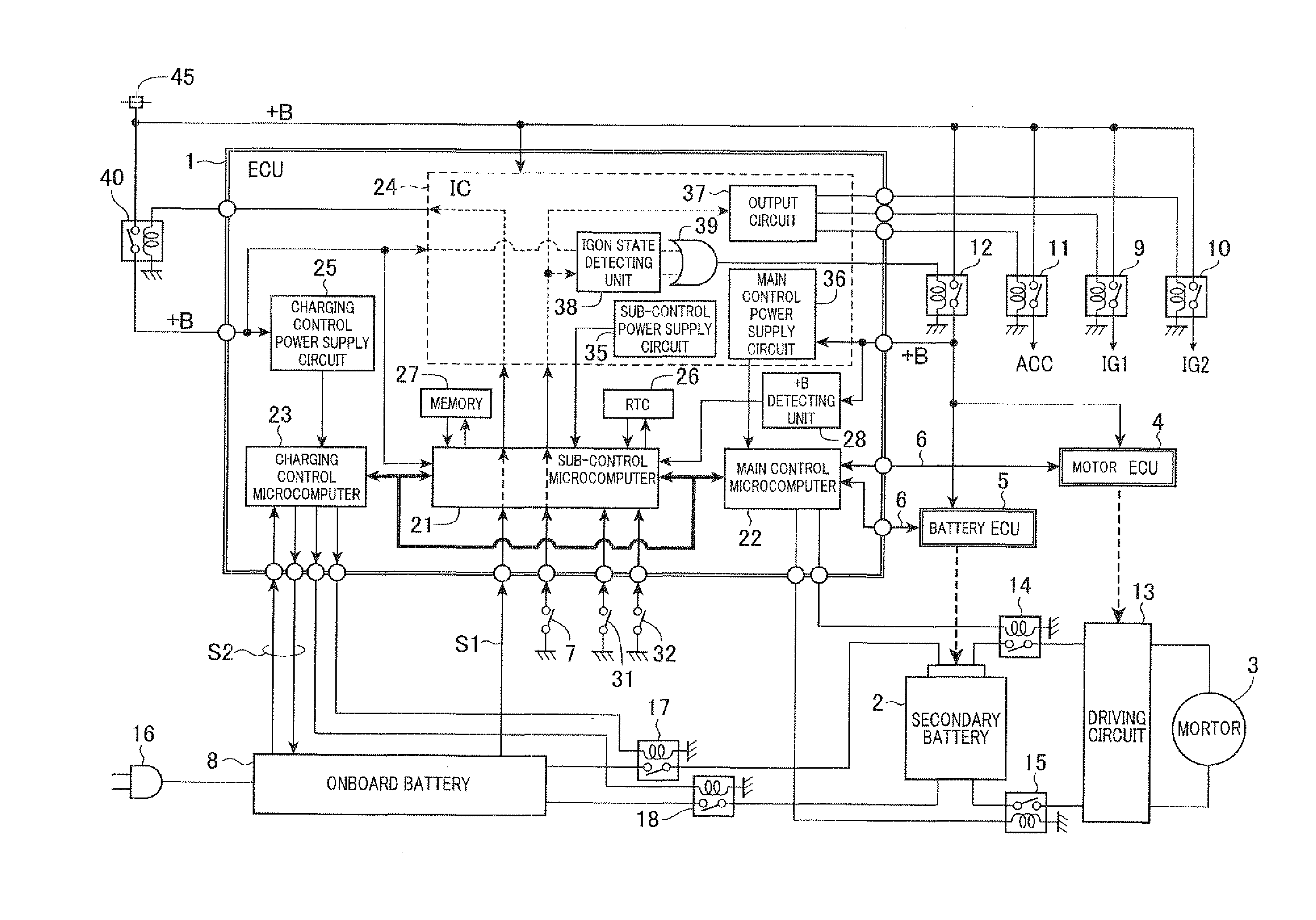
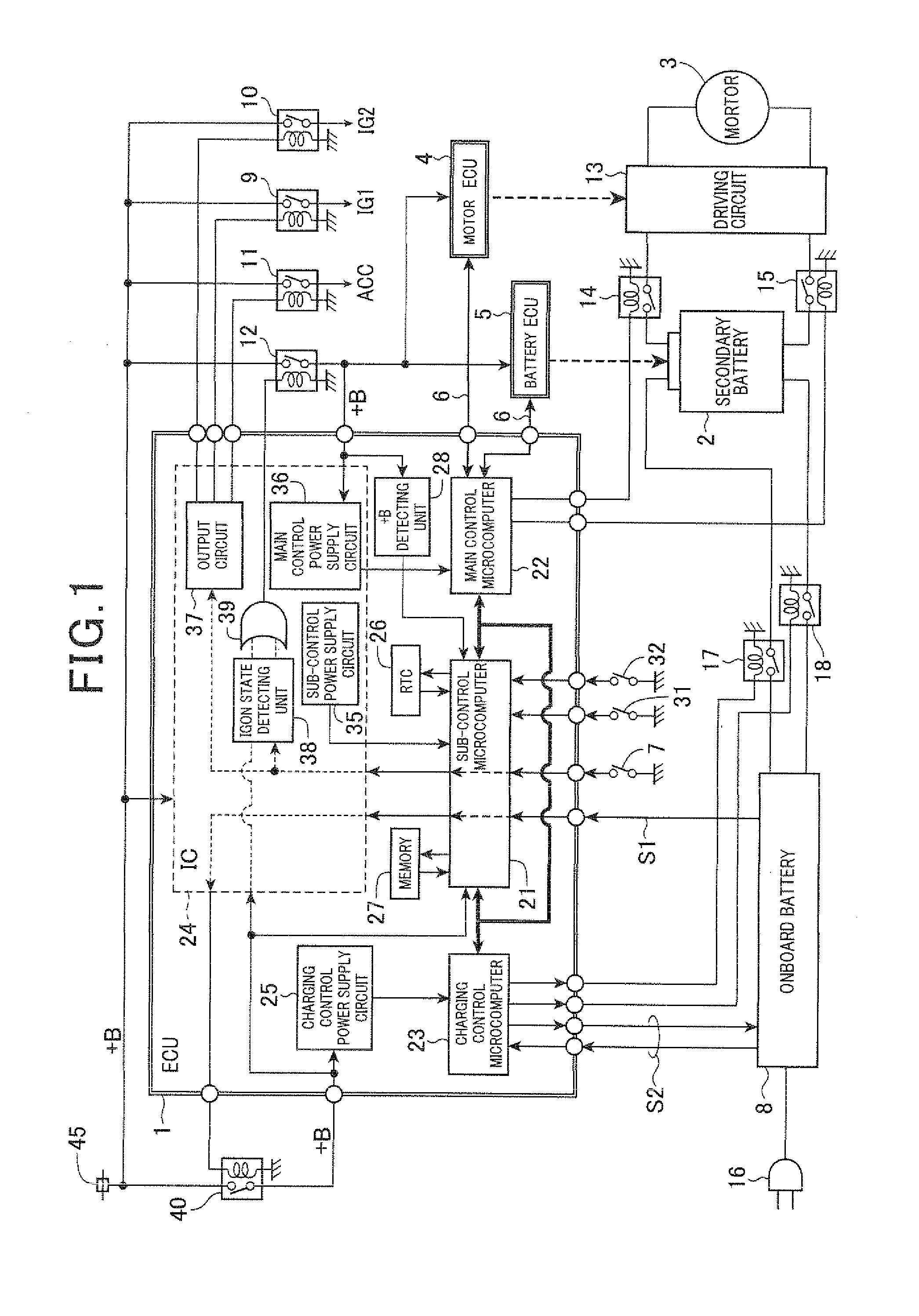
[0032]An electronic control unit (ECU) acting as an onboard charging control apparatus will be described. FIG. 1 is a block diagram of the ECU 1 according to the first embodiment. This ECU 1 is mounted on a vehicle such as a plug-in hybrid vehicle. Further, an internal combustion engine (not shown) acting as a driving power source is mounted on this vehicle to provide running force to the vehicle.

[0033]As shown in FIG. 1, the vehicle is provided with a secondary battery 2 and an electric motor 3 driven by electric power of the battery 2. The motor 3 also provides running force to the vehicle. The battery 2 can be charged by an off-board power source (not shown) such as a power source for domestic use. This off-board power source is located outside the vehicle and applies an alternating current voltage of 100V or 200V, used on business at an office or the like.

[0034]An onboard battery 45 applies a battery voltage +B to the ECU 1, and the ECU 1 is operated. This ECU 1 has a function f...

second embodiment

[0189]FIG. 10 is a block diagram of an ECU 50 mounted on a vehicle according to the second embodiment. As shown in FIG. 10, the ECU 50 differs from the ECU 1 shown in FIG. 1 in that the ECU 50 has a sub-control microcomputer 51 in place of the microcomputer 21 and is not provided with the circuit 25 or the microcomputer 23. The ECU 50 controls an onboard charger 52 to charge off-board electricity to the secondary battery 2. The charger 52 is provided with a charging control power supply circuit and a charging control microcomputer 54.

[0190]The operation of the ECU 50 differing from the operation of the ECU 1 will be described. When the plug 16 of the charger 8 is inserted into a socket outlet of the off-board power source, off-board electricity is supplied to the charger 52, the charger 52 outputs a plug-in relay signal to the relay 40 in addition to a charging start signal S1 outputted to the microcomputer 51. In response to the plug-in relay signal, the relay 40 is turned on, elec...

third embodiment

[0194]FIG. 11 is a block diagram of an ECU 60 mounted on a vehicle according to the third embodiment. As shown in FIG. 11, the ECU 60 differs from the ECU 50 shown in FIG. 10 in that the ECU 60 has a well-known ignition switch (or a mechanical key) 61 in place of the switch 7, the detecting unit 38 and the circuit 37. The ignition switch 61 has a key receiving inlet. When the user inserts an ignition key into the inlet of the switch 61 and turns the key by one of predetermined angles, the relays 9 to 11 are set in the OFF state, the ACCON state or the IGON state. More specifically, when the key placed at the OFF position is turned to the ACC position, only the ACC relay 11 is turned on while the relays 9 and 10 are maintained to the OFF state together. When the key is turned to the IGON position though the ACC position, the relays 9 and 10 are turned on in addition to the relay 11 turned on. When the key placed at the ACC position or the IGON position is turned back to the OFF posit...


PUM


Abstract

A vehicle has an ECU, a battery being chargeable with off-board electricity and a motor driven by electric power of the battery. The ECU has a microcomputer to receive an operation time each time a user sets the ECU in an operation state, prepare a frequency of operation times for each time zone, and set a time of the time zone corresponding to the high frequency as a charging end target time. When the microcomputer receives a signal from an onboard charger connected with an off-board power source, the microcomputer sets a charging schedule such that the battery charged by the charger according to the schedule is set in a fully-charged state at the charging end target time. The microcomputer controls the charger to charge the battery according to the schedule and to set the battery in the fully-charged state at the charging end target time.

Description

CROSS-REFERENCE TO RELATED APPLICATION[0001]This application is based upon and claims the benefit of priority of the prior Japanese Patent Application 2010-042656 filed on Feb. 26, 2010, so that the contents of which are incorporated herein by reference.BACKGROUND OF THE INVENTION[0002]1. Field of the Invention[0003]The present invention relates to an onboard charging control apparatus which is mounted on a vehicle having a secondary battery being chargeable with off-board electricity and a motor driven by electric power of the battery and controls a charge to the battery.[0004]2. Description of Related Art[0005]In a type of vehicle, driving force required to run the vehicle can be obtained by driving a motor by electric power of a battery. Especially, in a recent year, for the purpose of environmental protection, conservation of resources, enhancement of fuel economy and the like, a vehicle with a motor-driving secondary battery being chargeable by an off-board (or external) power ...

Claims


Application Information

Patent Timeline
IPC IPC(8): H02J7/00
CPCH02J7/041B60L2240/80B60L2260/46B60L2260/58Y02T10/7072Y02T90/14Y04S10/126Y04S30/14B60L53/14B60L53/64B60L53/63B60L53/11B60L58/16B60L58/12H02J7/0071H02J2310/48Y02E60/00Y02T10/70Y02T90/12Y02T90/167H02J7/04
Inventor SAKAI, NAOTO
Owner DENSO CORP
Why Eureka
Try Eureka