Comparator circuit provided with differential amplifier making logical judgment by comparing input voltage with reference voltage

a comparator circuit and differential amplifier technology, applied in the field of comparator circuits, can solve the problems of long time necessary for logical judgment of the comparator circuit, difficult signal processing, and very slow operation speed, and achieve the effects of reducing the logical judgment time of the signal processing, reducing the logical judgment time, and increasing the adaptive bias curren

Active Publication Date: 2011-09-01
SONY CORP
View PDF6 Cites 15 Cited by
  • Summary
  • Abstract
  • Description
  • Claims
  • Application Information

AI Technical Summary

Benefits of technology

[0044]Therefore, according to the comparator circuit of the invention, the adaptive bias current generator circuit generates and supplies an adaptive bias current for executing adaptive bias current control to the differential amplifier, based on the detected bias current and the detected through current, so as to allow the differential amplifier to operate with the bias current for a time interval of no logical judgment executed by the differential amplifier, and to allow the differential amplifier to operate by using the adaptive bias current obtained

Problems solved by technology

However, there is such a problem that the operating speed becomes very slow when the bias current IREF is designed to be a minute current having an order of nano-amperes.
However, there has been such a problem that time necessary for logical judgment of the comparator circuit becomes long and the signal processing becomes difficult when the tail current is designed to be a minute current.
Setting the bias current value IREF to an order of nano-amperes has had such a problem that the logical judgmen

Method used


Image

  • Comparator circuit provided with differential amplifier making logical judgment by comparing input voltage with reference voltage
  • Comparator circuit provided with differential amplifier making logical judgment by comparing input voltage with reference voltage
  • Comparator circuit provided with differential amplifier making logical judgment by comparing input voltage with reference voltage

Examples


first preferred embodiment

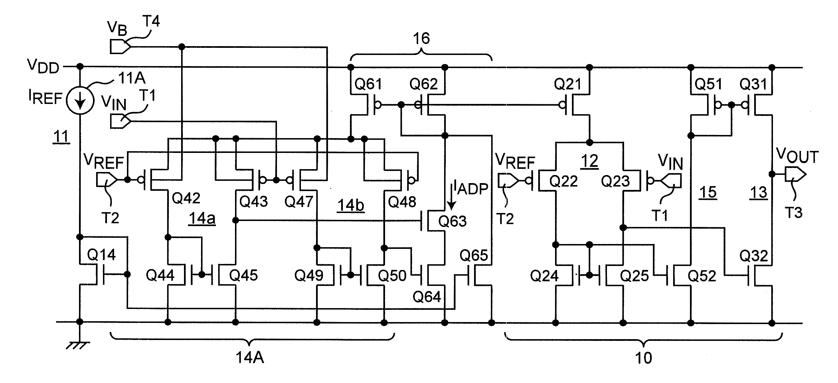
[0079]FIG. 7 is a circuit diagram showing a configuration of an adaptive bias current control system comparator circuit utilizing a body bias effect according to the first preferred embodiment of the invention. The aforementioned comparator circuit of NPS Inc. (FIG. 5) operates in a subthreshold region. Therefore, the technique for generating an offset voltage by the size ratio of the differential pair configured to include the two differential amplifiers 14a and 14b and the size ratio of the current mirror circuits has had such a problem that the size ratio, which is contained in the logarithmic term, produces small effects appearing as an offset voltage and only a minute offset voltage can be generated.

[0080]In the first preferred embodiment of the invention, a technique for more effectively generating the offset voltage was estimated. The idea of utilizing the two differential amplifiers 14a and 14b is identical to the technique of the comparator circuit of FIG. 5. However, in co...

second preferred embodiment

[0083]FIG. 9A is a circuit diagram showing a configuration of an adaptive bias current control system comparator circuit that utilizes the through current ISC of a CMOS inverter circuit according to the second preferred embodiment of the invention. In the configuration of the comparator circuit proposed by the first preferred embodiment and its modified preferred embodiment, two differential amplifiers 14a and 14b are required for the adaptive bias current generator circuit 14. For the above reasons, there is such a problem that the mounting scale of the circuit is relatively large. Accordingly, a circuit configuration capable of remarkably reducing the circuit scale was estimated. It is noted that the through current ISC of the CMOS inverter circuit is defined as a current that flows when the MOSFETs are both turned on.

[0084]FIG. 9A is characterized by including such a circuit configuration that the output voltage of the differential amplifier 12 is monitored by an inverter circuit...

third preferred embodiment

[0091]FIG. 11 is a circuit diagram showing a configuration of a comparator circuit according to the third preferred embodiment of the invention, in which the leak current of the inverter 13 of the final stage is reduced to solve the problem of the comparator circuit of FIG. 10. In order to solve the problem of the comparator circuit of FIG. 10, the circuit is characterized by including an adaptive bias current generator circuit 19B, in which a generator circuit of the minute bias current IREF and a generator circuit of the adaptive bias current IADP of the through current ISC are configured to include separate current mirror circuits.

[0092]In the differential amplifier 12A of FIG. 11, the bias current IREF is applied as a bias to the differential amplifier 12A via a current mirror circuit configured to include MOSFETs Q11 and Q21a. Likewise, the adaptive bias current IADP of the through current ISC of the inverter circuit 17 is applied as a bias to the differential amplifier 12 via ...


PUM


Abstract

In a comparator circuit having a differential amplifier, which makes a logical judgment by comparing an input voltage with a reference voltage, generates and outputs a resulting output voltage thereof, a current source generates and supplies a bias current of a predetermined minute current to the differential amplifier, and a first inverter circuit inverts a differential voltage from the differential amplifier. An adaptive bias current generator circuit detects the bias current of the current source, and a through current of the first inverter circuit. The adaptive bias current generator circuit generates and supplies an adaptive bias current for executing adaptive bias current control to the differential amplifier to allow the differential amplifier to operate with the bias current upon no logical judgment, and to allow the differential amplifier to operate by using the adaptive bias current obtained by increasing the bias current upon logical judgment.

Description

BACKGROUND OF THE INVENTION[0001]1. Field of the Invention[0002]The present invention is related to a comparator circuit, which is a fundamental component circuit of the integrated circuit technology, and is related, in particular, to a circuit technology to achieve power reduction of the comparator circuit.[0003]2. Description of the Related Art[0004]A variety of electronic equipments around us are currently configured to include semiconductor integrated circuits. Power reductions of the semiconductor integrated circuits have been achieved by scale shrinkage of device components and power supply voltage reduction. However, it is estimated that the device scale shrinkage approaches its limit, and a low-power consumption design technology making good use of circuit technologies is indispensable in order to achieve a further power reduction.[0005]The comparator circuit is one of the most fundamental component circuits among electronic circuits. FIG. 1 shows a circuit symbol diagram of...

Claims


Application Information

Patent Timeline
IPC IPC(8): H03K5/22
CPCH03K5/2481
Inventor HIROSE, TETSUYATSUBAKI, KEISHINUMA, MASAHIRO
Owner SONY CORP
Why Eureka
Try Eureka