
Method for the preparation of a hydrocarbon synthesis catalyst and the use thereof in a hydrocarbon synthesis process

a hydrocarbon synthesis and catalyst technology, applied in the preparation of oxygen-containing compounds, metal/metal-oxide/metal-hydroxide catalysts, liquid hydrocarbon mixture production, etc., can solve the problem of difficult control of the chemistry involved in the fusion process, the relative inability of the fused catalyst to respond to chemical promotion, and the restriction of the optimization of the selectivity of the catalyst. , to achieve the effect of reducing production and maintenance costs and improving quality control

Inactive Publication Date: 2011-09-01
SASOL TEKHNOLODZHI PROPRIEHJTEHRI LTD
View PDF8 Cites 15 Cited by
  • Summary
  • Abstract
  • Description
  • Claims
  • Application Information

AI Technical Summary

Benefits of technology

[0032]The inventors believe that by following the process according to the invention, segregation of the catalyst promoters is inhibited such that the homogeneous spread of catalyst promoter in the individual solid particles of hydrocarbon synthesis catalyst will provide substantially the same hydrocarbon product selectivity and will allow for better quality control in respect of the composition of the hydrocarbon synthesis catalyst.
[0033]It is also believed that the hydrocarbon synthesis catalyst prepared according to the method herein described has at least similar, if not better, mechanical strength when compared to conventional hydrocarbon synthesis catalysts prepared by means of milling a typically fused iron oxide catalyst, which is prepared in the conventional manner known in the art. The inventors envisage that as a result, subsequent catalyst break-up in the synthesis reactor and catalyst carry over with hydrocarbon products will be minimised.
[0034]It will be appreciated that the above method also provides the advantage that the hydrocarbon synthesis catalyst is formed directly from the melt and may be dispersed into solid particles of a desired particle size distribution, by varying the pressure of the fluid stream, so that the steps in conventional methods for preparing fused hydrocarbon synthesis catalysts, such as casting, crushing, milling, classification and cyclone separation are done away with thereby decreasing the production and maintenance costs of the overall catalyst manufacturing process.
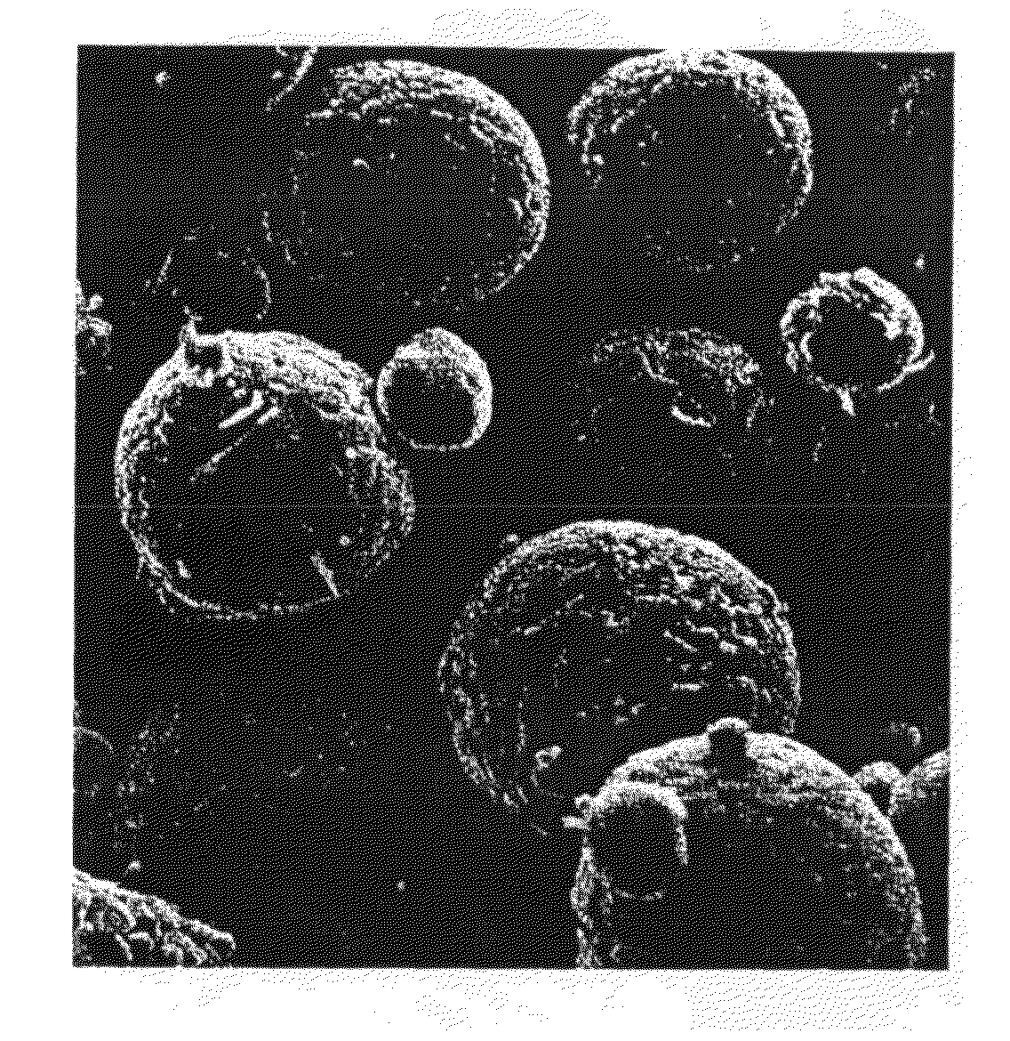
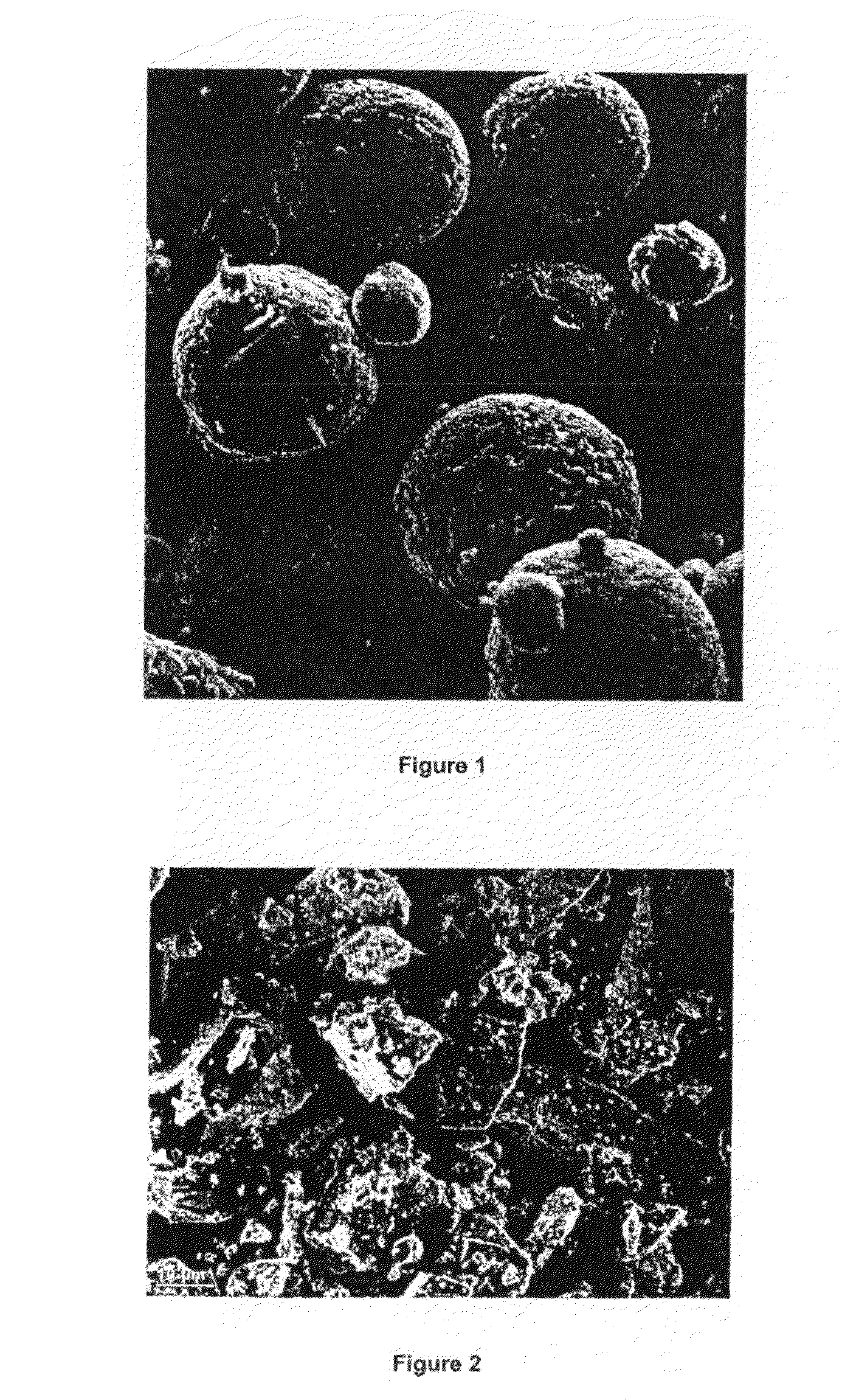
[0040]It is believed by the inventors that the substantially spherical shape of the solid particles of hydrocarbon synthesis catalyst shall improve the flow properties of the catalyst when used in a hydrocarbon synthesis process, preferably in a Fischer Tropsch Process, and more preferably in a fluidised High Temperature Fischer Tropsch Process. This in turn will result in better fluidization in the reactor zone and stable operation of the cyclones in the commercial SAS reactors due to a lower change in pressure in the dipleg of the cyclone.
[0045]According to a third aspect of the invention, there is provided the use of a hydrocarbon synthesis catalyst in a Fischer Tropsch reaction. Preferably the FT reaction is an HTFT reaction and preferably the hydrocarbon synthesis catalyst is reduced.

Problems solved by technology

The chemistry involved in the fusion process is complicated and difficult to control.
Thus the fused catalyst is relatively unresponsive to chemical promotion and optimization of the selectivity of this catalyst is restricted.
The high fusion temperature also results in the volatilization of some of the promoters, such as potassium oxide.
This results in the establishment of a promoter concentration gradient from the segment of material solidifying first to that segment solidifying last which consequently gives rise to undesirably higher levels of promoter in the latter section.
This high carbon make results in a fast decline in catalyst bed density in the fluidised reactors and hence places a limit on the catalyst lifetime.

Method used


Image

  • Method for the preparation of a hydrocarbon synthesis catalyst and the use thereof in a hydrocarbon synthesis process
  • Method for the preparation of a hydrocarbon synthesis catalyst and the use thereof in a hydrocarbon synthesis process
  • Method for the preparation of a hydrocarbon synthesis catalyst and the use thereof in a hydrocarbon synthesis process

Examples


example 1

Preparation of a Standard Conventional Fused Hydrocarbon Synthesis Catalyst (Hereinafter Referred to as “Standard Fused Catalyst”) and a Hydrocarbon Synthesis Catalyst According to the Invention

[0067]A standard fused catalyst was prepared by fusing iron oxide in the form of magnetite together with the chemical promoter K2O and the structural promoters MgO or Al2O3 in an electric arc furnace at a temperature of approximately 1650° C. The melt was then poured into pans on a continuous casting belt with the result that segregation of the promoter concentration occurs in the cast material during solidification such that the concentration gradient varies from that segment of the material solidifying first to that segment of the material solidifying last. The resultant ingots of fused catalyst were then crushed into pieces and milled. It will be appreciated that the standard fused catalyst was prepared in a manner well known in the art.

[0068]A hydrocarbon synthesis catalyst according to t...

example 2

Particle Size of a Hydrocarbon Synthesis Catalyst Prepared According to the Invention

[0072]The particle size distributions of the rapidly quenched hydrocarbon synthesis catalyst are set out in Table 2 below, the varying particle sizes being achieved by varying the pressure of the water during atomization. It is envisaged that the method according to the invention provides the advantage that one does not have to go through the steps of casting, crushing, milling, classification and cyclone separation to achieve a catalyst having a particular particle size and that this can quite economically be achieved by varying the water pressure as demonstrated in Table 2 below.

TABLE 2Particle Size Distribution of rapidly quenched HTFTcatalyst produced at different water pressures.Percentage smaller than50 bar75 bar100 bar150 barSizewaterwaterwaterwater(micron)pressurepressurepressurepressure24910010010010017694100991001257870958588564885716233307057441419554631311413522162925160.531918110111107....

example 3

Homogenous Distribution of Catalyst Promoters in a Hydrocarbon Synthesis Catalyst Prepared According to the Invention

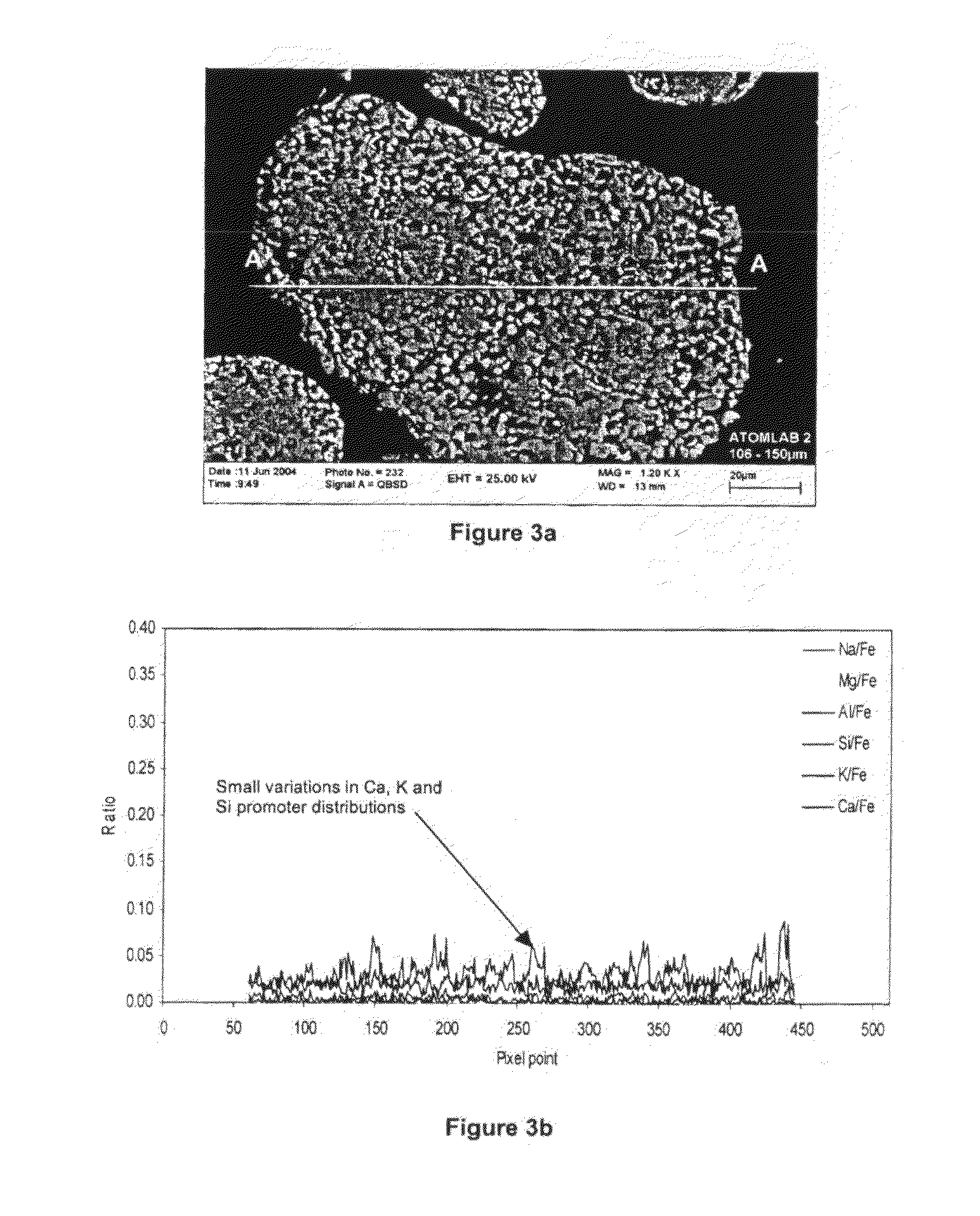
[0075]As discussed above, a further advantage of the method according to the invention is that the distribution of catalyst promoters, in the particles of the hydrocarbon synthesis catalyst prepared according to the invention, is substantially homogeneous thereby providing similar if not better hydrocarbon synthesis performance in an FT process. This is demonstrated below.

[0076]Further, the selectivity of each particle of hydrocarbon synthesis catalyst prepared according to the method of the invention will have substantially the same hydrocarbon selectivity since the promoter compositions of the catalyst particles (alkalinity indices) are substantially the same for the different particle fractions (see Table 4 below) whereas the alkalinity indices for the particle fractions of a standard fused and milled catalyst known in the art and shown in Table 3 below, differ sig...


PUM

PropertyMeasurementUnit
pressureaaaaaaaaaa
temperatureaaaaaaaaaa

Abstract

This invention relates to a method for the preparation of a hydrocarbon synthesis catalyst, preferably, a Fischer Tropsch synthesis catalyst. The invention also extends to the use of a catalyst prepared by the method according to the invention in a hydrocarbon synthesis process, preferably, a Fischer Tropsch synthesis process. According to a first aspect of the invention there is provided a method for the preparation of a hydrocarbon synthesis catalyst, the method including the steps of: (a) providing a melt including a mixture of at least one metal iron oxide and a catalyst promoter selected from the group consisting of at least one of a source of an alkali metal and a source of an alkali earth metal; (b) subjecting the melt to a fluid stream so as to thereby disperse the melt into droplets including the metal iron oxide and the catalyst promoter; and (c) quenching the droplets of the melt so as to form the hydrocarbon synthesis catalyst in the form of solid particles including the metal oxide and the catalyst promoter.

Description

FIELD OF THE INVENTION[0001]This invention relates to a method for the preparation of a hydrocarbon synthesis catalyst, preferably, a Fischer Tropsch synthesis catalyst. The invention also extends to the use of a catalyst prepared by the method according to the invention in a hydrocarbon synthesis process, preferably, a Fischer Tropsch synthesis process.BACKGROUND TO THE INVENTION[0002]A Fischer-Tropsch process comprises the hydrogenation of CO in the presence of a catalyst based on metals, such as iron, cobalt and ruthenium. The products formed from this reaction are water, gaseous, liquid and waxy hydrocarbons which may be saturated or unsaturated. Oxygenates of the hydrocarbons such as alcohols, acids, ketones and aldehydes are also formed. The carbon number distribution of the products follow the well-known Anderson-Schulz-Flory distribution.[0003]The Fischer-Tropsch process can be described as a heterogeneous surface catalyzed polymerization reaction. The reaction entails the h...

Claims


Application Information

Patent Timeline
Patent Type & Authority Applications(United States)
IPC IPC(8): B01J23/78B01J23/02C07C1/02
CPCB01J23/78B01J23/8892B01J35/023C10G2/332B01J37/0072B01J37/0081B01J35/08B01J35/40B01J35/51
Inventor LABUSCHAGNE, JOHAN
Owner SASOL TEKHNOLODZHI PROPRIEHJTEHRI LTD
Learn More