Magnetic resonance imaging apparatus, initial state creation method, optimum intensity determination method, and magnetic resonance imaging method

Active Publication Date: 2011-09-01
FUJIFILM HEALTHCARE CORP
View PDF7 Cites 14 Cited by
  • Summary
  • Abstract
  • Description
  • Claims
  • Application Information

AI Technical Summary

Benefits of technology

[0015]In accordance with the present invention, it is possible to reduce measurement tim

Problems solved by technology

For this reason, there are cases that the flip angles of the spin differ depending on the region of the

Method used


Image

  • Magnetic resonance imaging apparatus, initial state creation method, optimum intensity determination method, and magnetic resonance imaging method
  • Magnetic resonance imaging apparatus, initial state creation method, optimum intensity determination method, and magnetic resonance imaging method
  • Magnetic resonance imaging apparatus, initial state creation method, optimum intensity determination method, and magnetic resonance imaging method

Examples


first embodiment

[0016]The first embodiment to which the present invention is applied will be described below referring to the diagrams. In the entire diagrams, the same function parts are represented by the same reference numerals, and the duplicative description thereof is omitted.

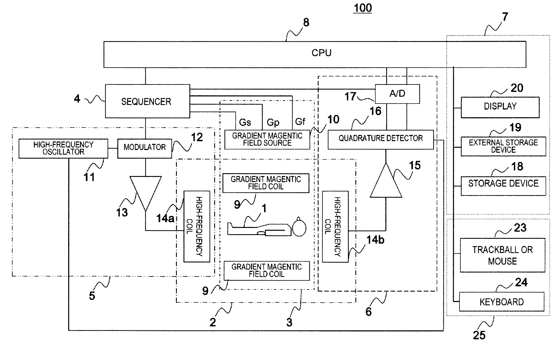
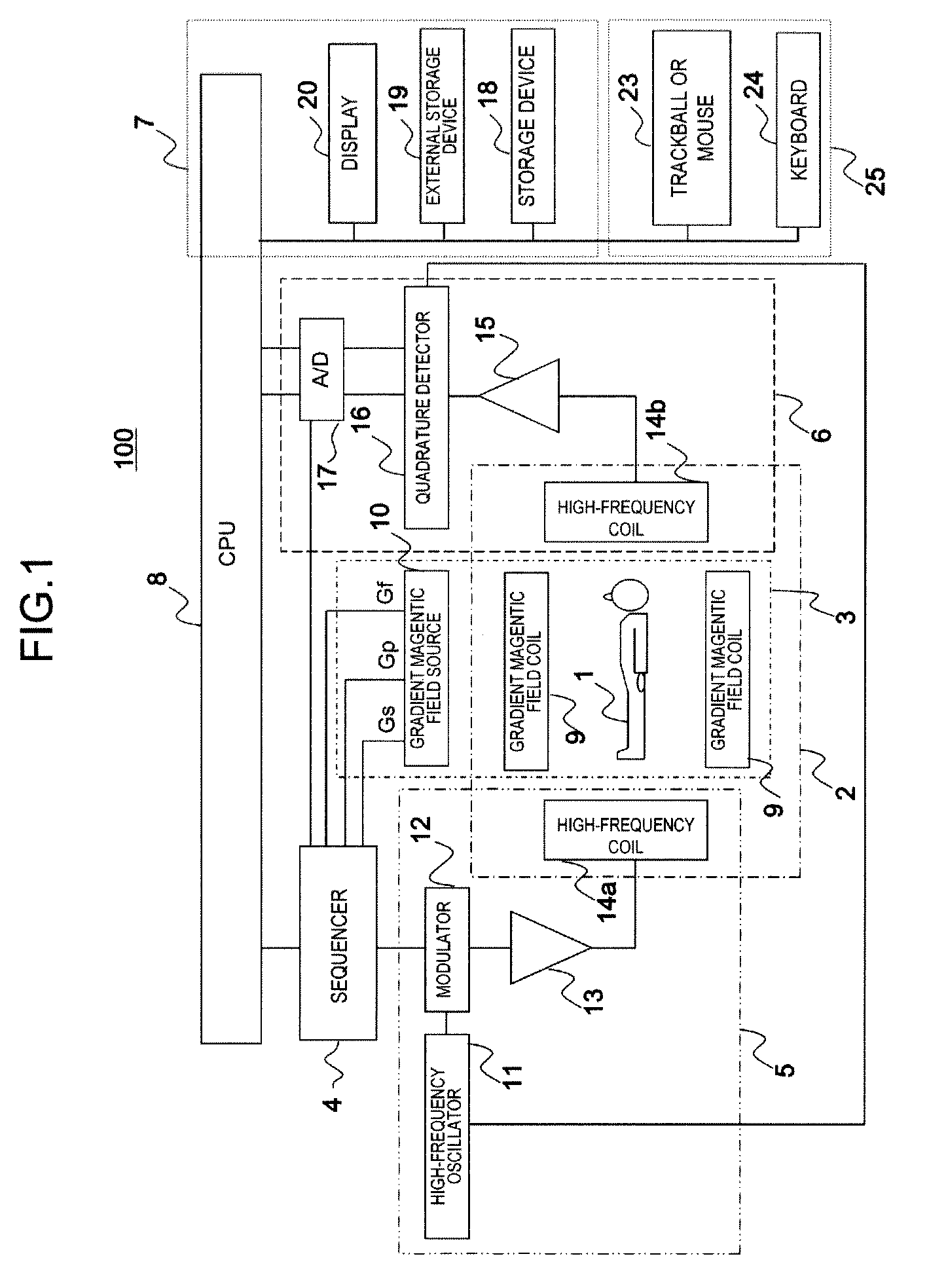
[0017]First, the overall overview of an example of the MRI apparatus related to the present embodiment will be described. FIG. 1 is a block diagram showing the general configuration of the MRI apparatus related to the present embodiment. MRI apparatus 100 is for obtaining a tomographic image of an object to be examined using NMR phenomenon, and comprises static magnetic field generation system 2, gradient magnetic field generation system 3, transmission system 5, reception system 6, signal processing system 7, sequencer 4 and central processing unit (CPU) 8.

[0018]Static magnetic field generation system 2 is for generating a uniform static magnetic field in the space around object 1 in the direction orthogonal to the body...

second embodiment

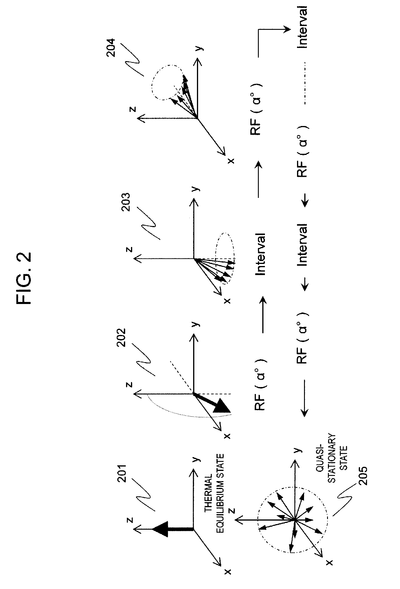
[0049]Next, the second embodiment to which the present invention is applied will be described. In the quasi-stationary generation process of the first embodiment, the quasi-stationary state generating RF pulse is repeatedly applied at the same flip angle in the same direction. However, the application direction of the quasi-stationary state generating RF pulse to be repeatedly applied is varied in the present embodiment. The flip angle stays the same. Configuration of the present embodiment will be described below exemplifying the case that the peak value of the echo signal is used for determining the reference pulse, focusing on the differences from the first embodiment.

[0050]In the present embodiment, application direction of the quasi-stationary state generating RF pulse to be repeatedly applied by the quasi-stationary state generation unit is varied as mentioned above. That is, application direction 8 is not constant as in the first embodiment, and is changed upon application. T...

third embodiment

[0062]Next, the third embodiment to which the present invention is applied will be described. In the present embodiment, a spoiler gradient magnetic field is applied after the quasi-stationary state generating RF pulse is applied in the quasi-stationary state generation process. By applying the spoiler gradient magnetic field, transverse magnetization is saturated (transverse magnetization is eliminated), and transition to the quasi-stationary state can be expedited. Configuration of the present embodiment will be described below focusing on the difference from the first embodiment. In the present embodiment also, the case of using the peak value of the echo signal will be exemplified for determination of the reference pulse.

[0063]As stated above, the spoiler gradient magnetic field is to be applied during application of the quasi-stationary state generating RF pulse in the present embodiment. The outline of the quasi-stationary state generation process to be executed by the quasi-s...


PUM


Abstract

This aims to shorten the time period, which is required for optimizing a radio-frequency magnetic field pulse intensity, thereby to shorten the measurement time period of an MRI entirety.
In the operation for optimizing the radio-frequency magnetic field pulse intensity, an initial state for applying radio-frequency magnetic field pulses is intentionally created for a short time period, thereby to shorten the radio-frequency magnetic field pulse interval for the repeated applications.
The radio-frequency magnetic field pulses are repeatedly applied at a predetermined time interval sufficiently shorter than the relaxing time period of the radio-frequency magnetic field pulses, and the state in which the magnetic resonance signal intensity becomes a threshold value or less is set to an initial state.

Description

FIELD OF THE INVENTION[0001]The present invention relates to a magnetic resonance imaging (hereinafter referred to as “MRI”) apparatus that measures a nuclear magnetic resonance (hereinafter referred to as “NMR”) signal from hydrogen, phosphorus, etc. in an object to be examined and reconstructs images of density distribution or relaxation time distribution, etc. of nucleus, in particular to a technique that adjusts intensity of the high-frequency magnetic field to be applied.DESCRIPTION OF RELATED ART[0002]An MRI apparatus measures an object, particularly NMR signals produced from atomic nuclei spin which forms tissues of a human body, and reconstructs images of shape or function of the head region, abdominal region or four limbs, etc. 2-dimensionally or 3-dimensionally. In the MRI apparatus, the NMR signals that are phase encoded or frequency-encoded by a gradient magnetic field are measured as time-series data. The measured NMR signals are reconstructed as images by being 2-dimen...

Claims


Application Information

Patent Timeline
IPC IPC(8): A61B5/055
CPCG01R33/543G01R33/583G01R33/546
Inventor ARAI, KOICHI
Owner FUJIFILM HEALTHCARE CORP
Why Eureka
Try Eureka