
Frequency Agile Filter Using a Digital Filter and Bandstop Filtering

Inactive Publication Date: 2011-09-22
RPX CLEARINGHOUSE
View PDF5 Cites 48 Cited by
  • Summary
  • Abstract
  • Description
  • Claims
  • Application Information

AI Technical Summary

Benefits of technology

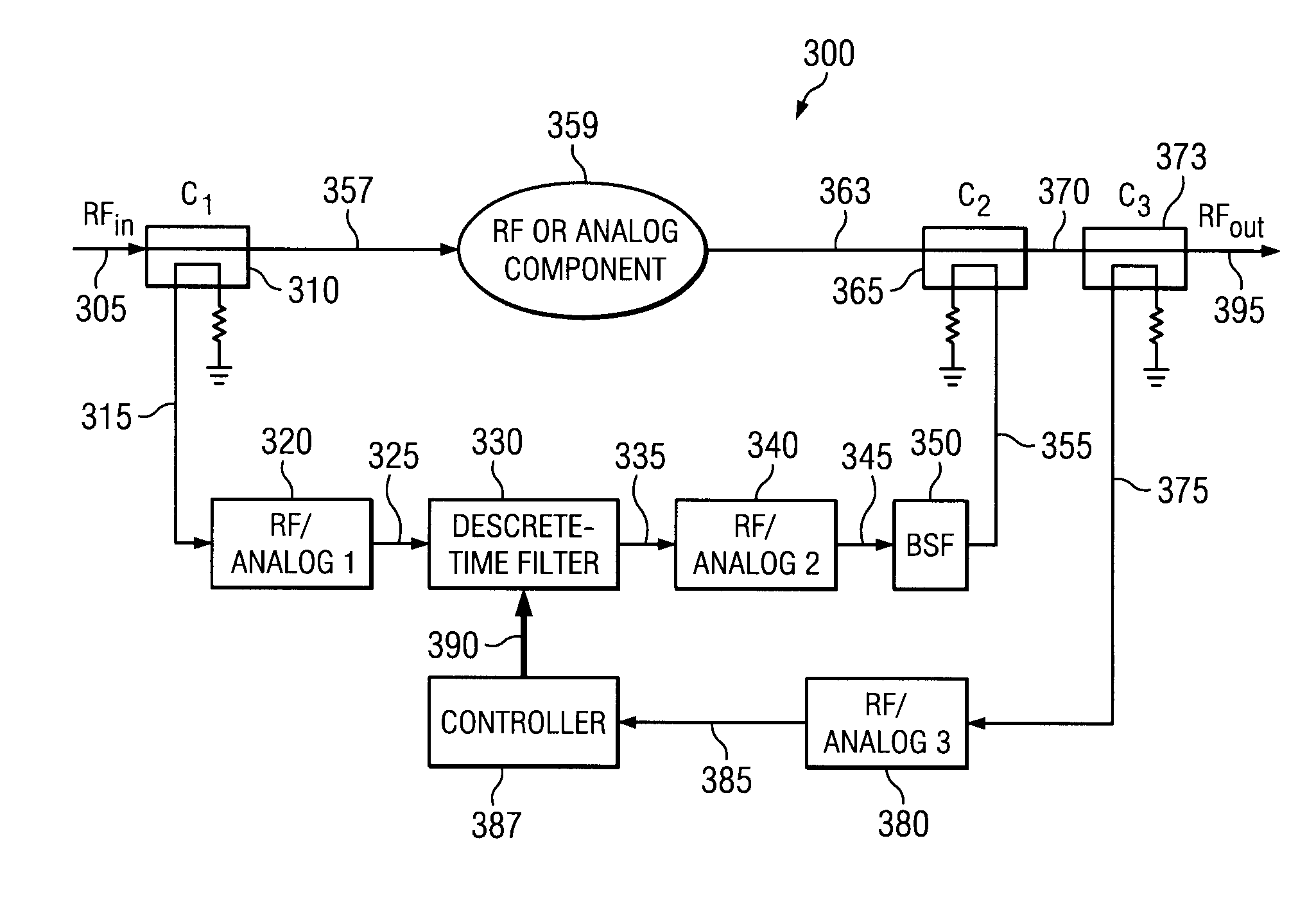
[0011]The present invention proposes a frequency agile multiple bandstop filter for use on a wireless communication system, multi-band radio architecture, system capable of spectrum re-farming and software defined radio. The system has a large dynamic range which can be used to handle high transmit power, or to handle weak receive signals in the presence of blockers. A notch or bandstop filter is used within the invention to relax the dynamic range requirements of the discrete-time filter when a large dynamic range exists between the passband and desired stopband signals.

Problems solved by technology

These filters are coupled-cavity filters with low-loss, high dynamic range and superior selectivity, but requiring mechanical tuning limits the reconfigurability of the filter in terms of carrier frequency range.
The number of RF paths, however, is limited to two or three paths since each additional path requires an additional splitter, combiner, tunable component, gain block and a time delay element.
Heat is dissipated into the tunable components of such known filters, and the Q-factor of tunable capacitors is limited.
The limited Q-factor of tunable elements means they cannot be used to filter high-power signals, and large insertion loss results for high-order configurations.
The former results in a large space commitment and possesses limited reconfigurability, while the latter results in increasing insertion loss.

Method used


Image

  • Frequency Agile Filter Using a Digital Filter and Bandstop Filtering
  • Frequency Agile Filter Using a Digital Filter and Bandstop Filtering
  • Frequency Agile Filter Using a Digital Filter and Bandstop Filtering

Examples


Embodiment Construction

[0024]The present invention is a hybrid RF and digital signal processor-based filter for multiband radio architectures, systems capable of spectrum re-farming and software defined radios. The invention can perform low-loss frequency agile multiple bandstop filtering at RF where a large dynamic range exists at the filter input between signals in stopband and passband. At the output of the transmitter the invention can be used to attenuate spurs, or noise within bands with strict emission constraints. At the input to the receiver the invention can be used to attenuate blockers or noise from the transmitter.

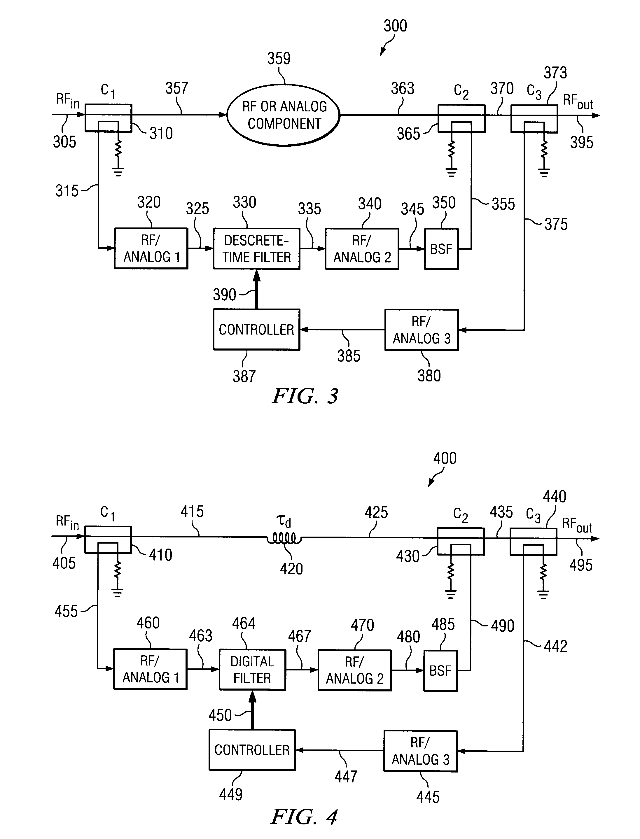
[0025]The present invention is a reconfigurable system that synthesizes and combines a cancellation signal with the output of an RF or analog component. The cancellation signal is synthesized using the signal tapped-off from the first coupler. The system can operate over a range of carrier frequencies, which means it is frequency agile. At a specific carrier frequency, the system ca...


PUM


Abstract

The present invention is a hybrid RF-digital signal processor-based filter for multiband radio architectures systems capable of spectrum re-farming and software defined radios. It performs low-loss frequency agile multiple notch filtering at RF where a large dynamic range exists at a filter input between signals in a stopband and passband. It is a frequency dependent signal attenuation apparatus having two paths connected together by directional couplers. The first path comprising a component such as a delay component or duplexer. The second path comprising a bandstop filter connected to a down converter, a digital filter, and an up converter. At the output of a power amplifier, the invention can be used to attenuate spurs, or noise within bands with strict emission constraints. At the input of a low noise amplifier, the invention can be used to attenuate blockers and transmitter noise outside of the receiver passband.

Description

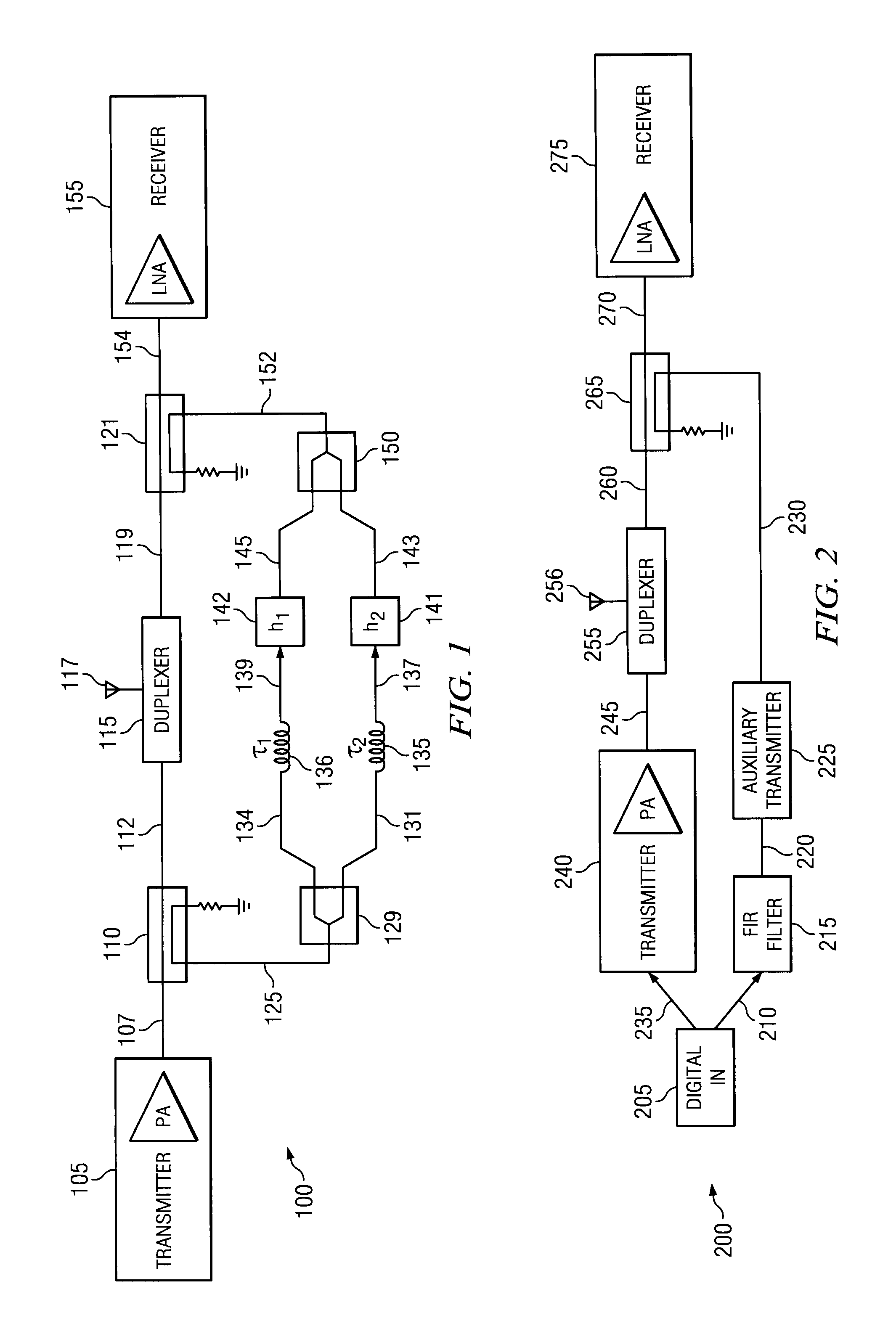
TECHNICAL FIELD OF THE INVENTION[0001]The present invention relates to a frequency agile duplex filter for use in RF filters and signal cancellation in a wireless communication system, multiband radio architecture, system capable of spectrum re-farming and software defined radio.BACKGROUND OF THE INVENTION[0002]Presently used RF filters in base stations include mechanically tunable RF filters. These filters are coupled-cavity filters with low-loss, high dynamic range and superior selectivity, but requiring mechanical tuning limits the reconfigurability of the filter in terms of carrier frequency range. What is needed is a filter and signal cancellation system that eliminates the need for mechanical tuning.[0003]Feed-forward configurations of RF discrete-time filters are also available. A known three path RF discrete-time feed-forward filter system is shown in FIG. 1 for improving duplexer isolation. In this figure, h1 and h2 are system blocks containing vector modulators. The symbol...

Claims


Application Information

Patent Timeline
IPC IPC(8): H04B3/04
CPCH03H11/344H04B1/525H04L25/08H04B1/10H04B1/1027H03H17/02H04B1/005H04B1/62
Inventor WYVILLE, MARK
Owner RPX CLEARINGHOUSE
Learn More