Induction switch

a high-voltage switch and induction switch technology, applied in the field of high-voltage switches, can solve the problems of high wear, unsuitable for standardised switch systems, and the failure of trigger systems, so as to achieve high charge carrier densities and high current rise rates

Inactive Publication Date: 2011-09-29
JOHANN WOLFGANG GOETHE UNIV FRANKFURT AM MAIN
View PDF11 Cites 1 Cited by
  • Summary
  • Abstract
  • Description
  • Claims
  • Application Information

AI Technical Summary

Benefits of technology

[0030]In a further preferred embodiment, the length of the apertures along an axial direction of the outer electrode corresponds to the extent of a section of the container which is surrounded by the coil. This ensures that the plasma generated inductively in the container can flow over the entire width of the plasma generation region through the aperture into the electrode gap. A particularly advantageous switching characteristic is produced in this manner.
[0031]In a preferred embodiment, the power source comprises at least one capacitor, which can be ...

Problems solved by technology

A disadvantage of the thyratron lies in the fact that the electrode surface of both the anode and the cathode is subject to severe erosion and thus high wear owing to the high current and power densities which arise.
The trigger system is therefore often completely destroyed or becomes unusable due to sputter effects after only a few thousand switching operations.
Laser triggers often cited in the technical literature avoid this problem and make possible very good switching characteristics, but are technically very complex (YAG laser with complex optics) and therefore currently unsuitable for standardised switch systems.
Such switches are however also limited to maximum reverse voltages of approximately 40 kV.
As well as the increased outlay on design, the di...

Method used


Image

  • Induction switch
  • Induction switch
  • Induction switch

Examples


Embodiment Construction

[0042]Further advantages and features of the device according to the invention and of the method according to the invention can be best understood using the detailed description of the drawings below, in which:

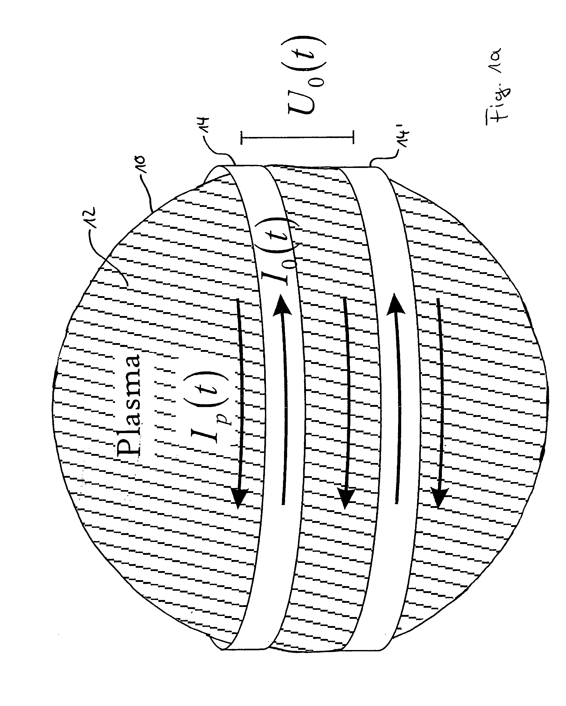
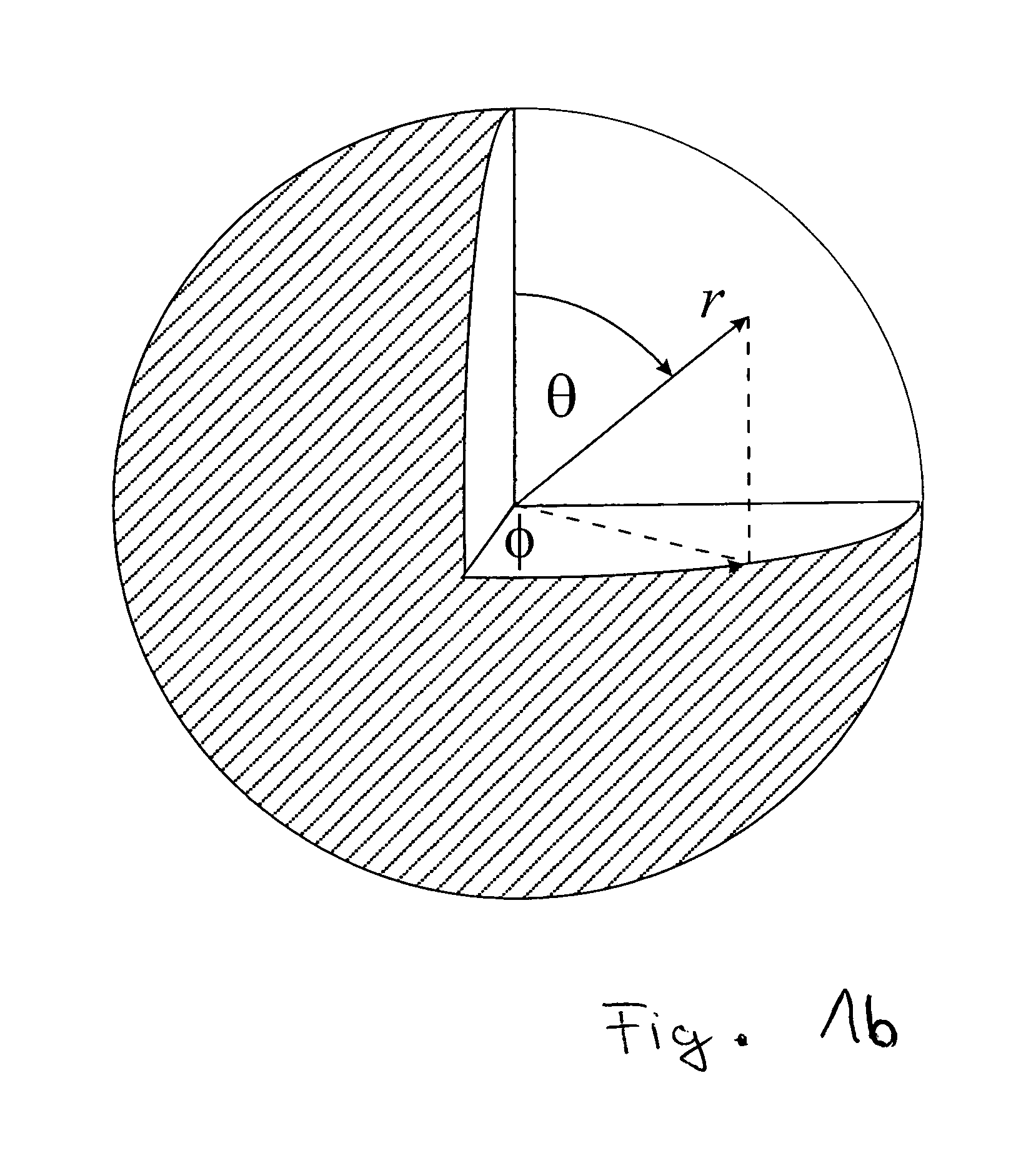
[0043]FIGS. 1a and 1b schematically show the principle of the inductive plasma generation;

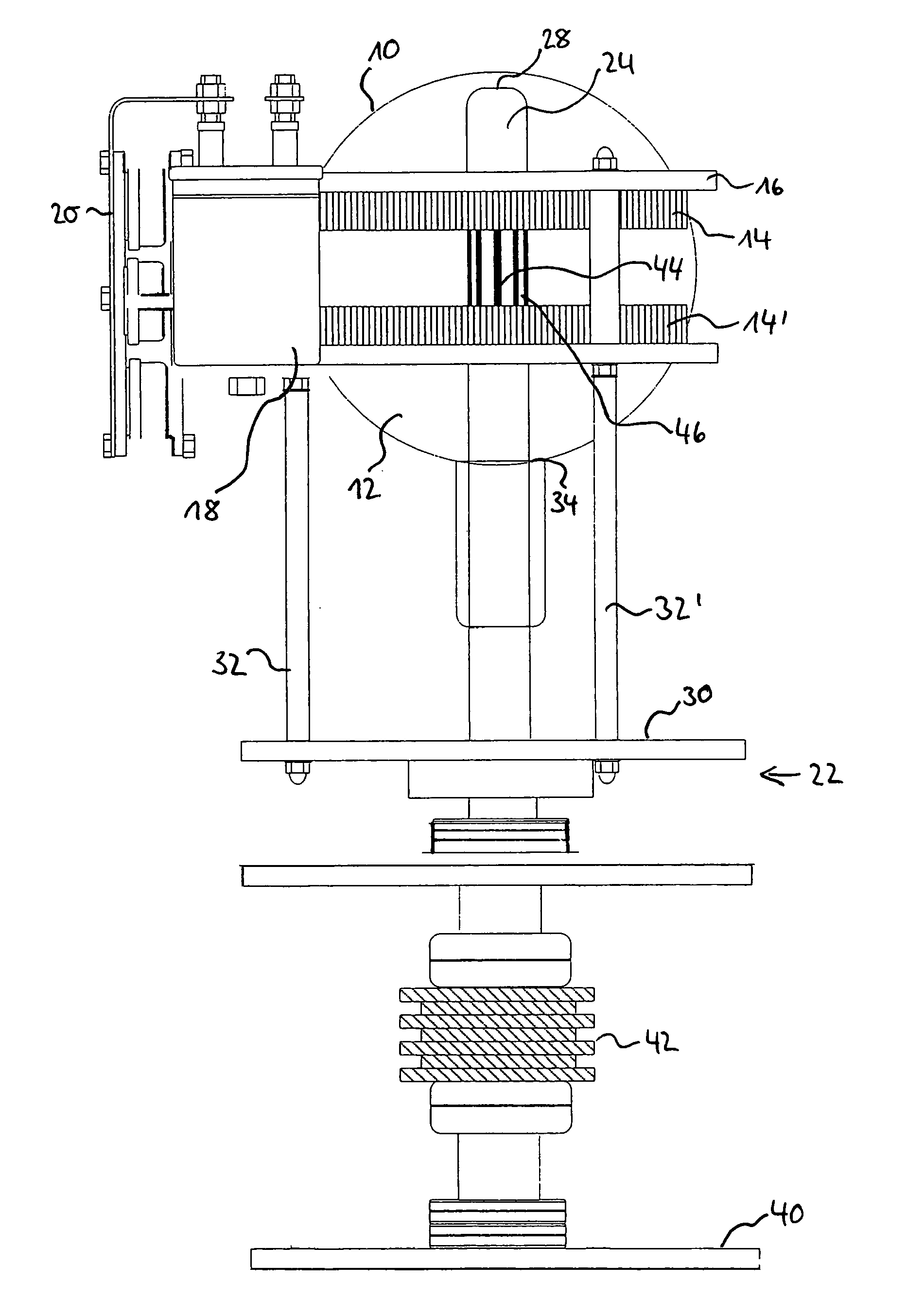
[0044]FIG. 2 shows the schematic structure of an induction switch according to the invention, with a container, an inductor, a power source and an electrode device with an electrode gap;

[0045]FIG. 3 shows a partial view of the electrode device with the electrode gap of FIG. 2; and

[0046]FIG. 4 shows an equivalent circuit diagram of the plasma generation device of FIGS. 2 and 3.

1. PRINCIPLES OF INDUCTIVE PLASMA GENERATION

[0047]Inductively coupled plasmas have been generated and studied for more than 100 years, as described for example in J. Hopwood, “Review of Inductively Coupled Plasmas for Plasma Processing”, Plasma Sources Science and Technology, I (1992), 109-116.

[0048]A device for indu...


PUM


Abstract

The invention relates to an induction switch comprising a discharge container filled with gas and a coaxially interleaved electrode device, and to a corresponding method for commutating high voltages. The inductive production of a dense plasma and the subsequent flooding of an electrode gap with the plasma ions produced enables the commutation of high currents in the kiloamp range when there are blocking voltages of over 500 kV. Such an induction switch only requires a single discharge gap, can be used over a very wide voltage range, and avoids the problem of electrode erosion as a result of the electrode-free energy coupling.

Description

FIELD OF THE INVENTION[0001]The invention relates to high voltage switches for switching currents in the kA range and in particular to high voltage switches which are switched by means of an inductively generated plasma discharge.PRIOR ART[0002]For switching high voltage sources, two groups of switches are known, gas discharge switches and semiconductor switches, which operate according to different physical principles.[0003]Gas discharge switches switch high currents by generating an arc discharge in a switch tube filled with a gas which can be ionised. An example is the thyratron, a tube rectifier with a hot cathode, which can be controlled by means of a grid and the structure of which is similar to a triode. An arc discharge, which turns the entire interspace into a conductive plasma, is initiated between the anode and cathode by application of a suitable control voltage to the grid electrode. The anode current can reach several thousand amperes depending on the configuration. Me...

Claims


Application Information

Patent Timeline
IPC IPC(8): H05H1/24
CPCH01T2/00H01J17/40
Inventor TESKE, CHRISTIANJACOBY, JOACHIM
Owner JOHANN WOLFGANG GOETHE UNIV FRANKFURT AM MAIN
Why Eureka
Try Eureka